

What are centrifugal pumps?
Centrifugal pumps are often utilized for pumping of low viscosity liquids e.g. water. The pump is particularly well adapted for pumping large volumes of low viscosity liquids.
Due to their high capacity flow rates, ease of maintenance and general robustness, the centrifugal pump is used extensively in many industrial applications all over the world.
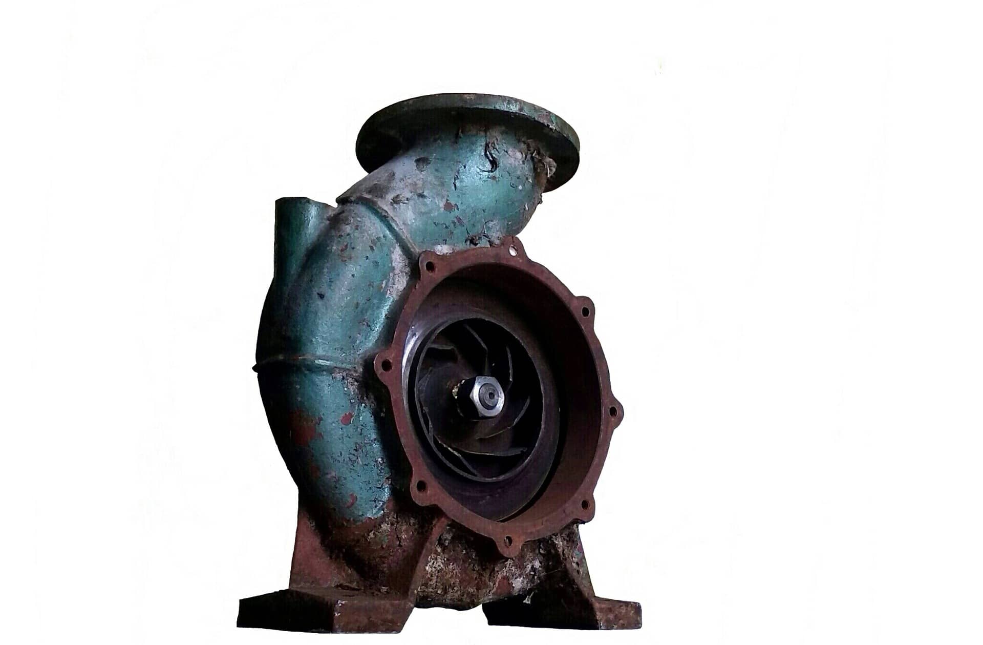
Radial Centrifugal Pump With Volute Casing
Centrifugal Pump Components
Centrifugal pumps are relatively simple in design and have few components. Some of the most common components are listed below.
Volute Casing and Diffuser
A volute casing or diffuser is used to convert kinetic energy to pressure.
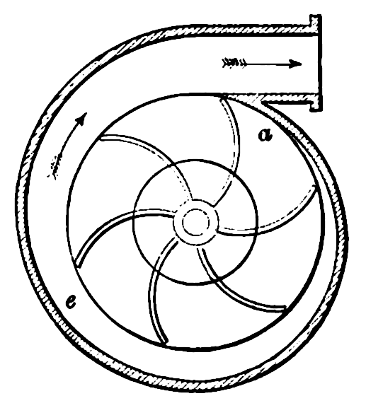
Volute Casing With Impeller (a)
An impeller rotates and imparts kinetic energy onto the liquid surrounding it due to friction. As the impeller rotates, the liquid moves towards the outer periphery of the impeller and its kinetic energy is changed to pressure.
Compression Packing and Mechanical Seals
Sealing of the pump is achieved using either compression packing (a.k.a. packing), or, a mechanical seal. Packing is a very old design (several thousand years) whilst mechanical seals are quite a recent development.

Packing is the cheaper of the two options although it has several disadvantages compared to a mechanical seal. These include:
- Gland packing presses physically against the shaft and slowly creates a groove on the shaft which may later need to be repaired.
- Contact between the gland and shaft creates friction which manifests itself as heat. This heat must be removed to prevent damage to the shaft and gland.
- Friction between the gland and the shaft means that the pump motor requires more amps for the same amount of work completed; thus an overall drop in efficiency occurs.
- Packing must be periodically tightened to maintain the correct leakage rate.
- The service life of packing is generally far shorter compared to a mechanical seal.
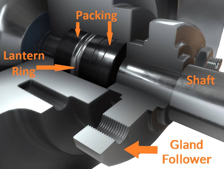
In addition to the above, a lantern ring may also need to be installed to allow cooling of the packing.
Mechanical seals do not suffer from the same problems associated with packing although they are more expensive and prone to leakage if the primary sealing faces are not completely clean.
Wear Rings
Wear rings are used to seal the space between the impeller and casing. Wear rings installed on the impeller are called ‘impeller wear rings’, whilst wear rings installed on the casing are referred to as ‘casing wear rings’.

If no wear rings were installed, the process liquid would be able to flow from the discharge to suction side of the pump in relatively large quantities and this leads to a drop in pump efficiency (as much as 4%). It is possible to operate a pump without wear rings, but resultant damage to the impeller and casing will occur and the cost of replacing an impeller or casing is far greater than the cost of replacing the wear rings.
Rubbing of an impeller against the casing may also lead to a process known as ‘galling’, which means the two metals have micro-welded together. In severe instances, galling can lead to the pump seizing completely.
Enjoying this article? Then be sure to check out our Centrifugal Pump Video Course! The course has a quiz, handbook, and you will receive a certificate when you finish the course. Enjoy!
How Centrifugal Pumps Work
The below video is an extract from our Introduction to Centrifugal Pumps Online Video Course.
Liquid is drawn in through the suction port (center hole in the casing) and discharged through the discharge port (hole on the top of the casing).

Once the liquid has passed through the suction port, it passes through an impeller and is discharged radially away from the eye of the impeller (center of the impeller). The liquid flows away from the eye of the impeller due to centripetal force, although this flowing motion is almost always attributed to centrifugal force, which is incorrect as centrifugal force is actually an imaginary (not real) force.

The impeller has vanes separated by channels, the liquid flows through these channels. Each channel has an increasing flow path area. As the flow path area expands, the liquid’s velocity decreases and the pressure increases. The relationship between area, velocity and pressure, is described by Bernoulli’s Principle.

Due to the unique shape of the volute casing, the liquid undergoes a further velocity decrease and pressure increase. The liquid is then discharged through the discharge port.
Classification by Flow
Centrifugal pumps are classified as either radial, axial or mixed flow.
Radial flow pumps discharge liquid perpendicular to the main pump shaft (90 degrees apart from the main pump shaft's orientation); this type of pump is ideal for many pressure and flow applications.

Radial Flow Centrifugal Pump
Mixed flow pumps discharge liquid at an angle exceeding 90 degrees relative to the pump shaft.

Mixed-Flow Centrifugal Pump
Axial flow pumps are used for low pressure, high flow, applications. Almost no radial force is imparted onto the liquid, but the pump is still classified as centrifugal because some small part of the liquid's movement is radial.

Axial Flow Centrifugal Pump
Classification by Impeller
Impellers are available in three common designs, these are closed, semi-open and open.

Open, Semi-Open and Closed Impellers
Closed – closed type impellers have two shrouds. The vanes of the impeller are completely sandwiched between the two shrouds. This type of impeller is very efficient for pumping low viscosity liquids with few suspended bodies (water, sea water, etc.). The closed type impeller has the greatest mechanical strength of all impeller designs due to the support given to the vanes from the shrouds.

Semi-Open/Semi-Closed – this type of impeller is also known as a ‘partially open’ or ‘partially closed’ type impeller. Semi-open impellers have only one shroud. This type of impeller is used for pumping liquids with a moderate amount of suspended bodies. Semi-open impellers are not as efficient as fully enclosed impellers because the pumped liquid is not guided directly along the vanes.

Open – open type impellers have no shrouds. This type of impeller is ideally suited for pumping high viscosity liquids (providing they do not foam when agitated) and liquids with many suspended bodies. Typical applications for this type of impeller would include sewage and paper pulp. Sometimes the centre of the impeller will also be fitted with a serrated knife to chop suspended bodies as they are drawn into the eye of the impeller.

Classification by Stage
Centrifugal pumps can be either single or multi-stage.
A single stage impeller is a pump with only one impeller. Single stage pumps typically use a volute casing, although a diffuser may be used if space is limited.

A multi-stage pump is a pump with more than one impeller. Multi-stage pumps typically use diffusers because installing a volute casing for each impeller is impractical due to size considerations.
Multi-stage pumps are referred to by the number of impellers installed on a common shaft, for example, a five stage pump is a multi-stage pump with five impellers (shown below).

Multi-stage pumps allow the pumped liquid to be passed through multiple impellers and diffusers before being discharged; this allows the pressure to be gradually increased at each pump stage.
Classification by Suction Type
Impellers can be either single suction or double suction.
Single suction impellers have only one suction inlet.
Double suction impellers have two suction inlets.

Single and Double Suction
Between Bearings or Overhung
Centrifugal pump impellers can be supported at one end in a cantilever arrangement, or, at both ends.
Impellers supported at only one end are referred to as overhung pumps, because the impeller is ‘hanging’ within the casing.

Impellers supported on both sides are referred to as between bearings pumps, because the impeller(s) is installed between the shaft bearings. Large centrifugal pumps and multi-stage centrifugal pumps are almost always between bearings pumps.
Pump Curves
Pump curves are used to find the optimum pump conditions based upon certain characteristics, such as the liquid being pumped, pressure desired and flow rate desired. The characteristics desired depends upon requirements; some pumps have many conditions that must be satisfied before they are put into service.
Two of the most important characteristics of a pump curve are the shut-off head and pump runout.
The shut-off head represents the maximum amount of static head that can be generated by the pump.
The runout value is the maximum permissible flow through the pump without the pump incurring damage.

Pump Curve
Shut-Off Head – is the maximum amount of static head (sometimes called ‘total head’) that can be generated by the pump when operating at a certain speed. Once the shut-off head is reached, there is no flow.
Example
Imagine pumping a liquid through a 10m long vertical orientated pipe. You do not know the shut-off head, so you begin to drill holes in the vertical pipe until water flows-out. You drill at 10m in height, then 9m in height and water flows-out when you drill at 8m in height. You then cut the top 1 metre of the vertical pipe off and can see that the water level is at approximately 8.5m. You see that there is no flow. The water level you see represents the shut-off head.
In our example, the ‘height’ can be classified as the ‘discharge head’, this is the pressure head that lifts the liquid from the pump discharge pipe to the final outlet.
The ‘static head’ (a.k.a. total head) is the difference in vertical height from the top of the liquid being pumped to the highest point where the liquid is discharged.
The shut-off head is the total head value when no flow occurs.

Total Pressure Head (static head)
Runout – is the maximum permissible flow through the pump without damaging the pump. High flow rates often lead to cavitation which is not desired.
Cavitation
Cavitation occurs due to pressure variations encountered by the liquid as it travels through the pump impeller. Entrained vapour bubbles form and collapse due to this sudden pressure change. Whilst cavitation is inconsequential on a small scale, it is very damaging to the pump when repeated thousands of times per second.

Effect of Pressure Change On A Vapour Bubble (cavitation)
Cavitation often makes the pump sound as if marbles are being shaken inside the pump casing. If cavitation is suspected, remedial action must be taken to reduce or stop the cavitation as soon as possible.
Gas Binding
The liquid being pumped can be thought of as an essential part of the pump. Without liquid, the pump will not operate correctly. Gas binding refers to a situation where too little liquid is present within the pump and a negative suction pressure cannot be obtained. If no negative suction pressure can be obtained, no liquid can be drawn into the pump and no flow will occur.
Note: Positive displacement pumps do not suffer from gas binding because these types of pump are self-priming (can pump air).
Priming
Pumps that can pump air are referred to as 'self-priming'. Unlike positive displacement pumps, a centrifugal pump cannot pump air and thus is not self-priming. It is normally a requirement that a head of pressure is available when the pump is started, this often means the pump is installed below the level of liquid being pumped (the liquid is drawn into the pump due to gravity). Another means of priming the pump is to use an additional pump to feed the main centrifugal pump until suction is obtained.

Pump Installed Below Liquid Being Pumped
3D Model Details
This 3D model shows all major components associated with a typical centrifugal pump, these include:
- Impeller
- Volute Casing
- Shaft
- Mechanical Seal
- Suction and Discharge Ports
- Shaft Key
- Bearing
- Nuts and Bolts
- Wear Rings
- Compression Packing
- Lantern Ring
This is a 3D model of a Centrifugal Pump.
3D Model Annotations
Discharge/Outlet
Fluid is discharged through this connection.
Suction/Inlet
Fluid is drawn into the impeller through this connection.
Wear Ring
An impeller wear ring is installed to reduce the clearance between the casing and impeller. Reducing the clearance reduces the amount of leakage from the discharge to suction side of the impeller; this ultimately improves the efficiency of the pump.
Impeller
Fluid flows into the eye of the impeller and then outwards radially. As the fluid moves outwards through the impeller vanes, its kinetic energy is converted to pressure energy. There are three types of centrifugal impeller, these are the closed, partially closed and open types; the type used depends upon what fluid is being pumped.
Volute Casing
Centrifugal pump casings are of the diffuser or volute type. Single stage pumps (one impeller) almost always utilise volute casings, whilst multistage pumps (>1 impeller) usually utilise diffuser casings.
Compression Packing
Compression packing seals the space between the shaft and casing. Compression packing is usually referred to simply as ‘packing’. An alternative to compression packing is the mechanical seal.
Stuffing Box
The area where the packing and lantern ring are installed is known as the ‘stuffing box’. The packing is literally ‘stuffed’ into this space. On this model, the annotation marker has been placed above the stuffing box.
Lantern Ring
Lantern rings are used to distribute cooling liquid to the packing. The liquid cools and lubricates the packing, which helps prevent it overheating.
Gland Follower
A gland follower is used to compress the packing, but it is important a leak rate be maintained through the packing. The leakage rate should be measured in drops per minute and the gland follower should be adjusted if the leakage rate becomes excessive.
Ball Bearings
Bearings carry the axial and radial loads generated by the pump when it is stationary and in service. The type of bearing used depends upon many factors, although ball bearings are considered a suitable bearing for many service applications. Ball bearings are a type of anti-friction bearing.
Additional Resources
https://en.wikipedia.org/wiki/Centrifugal_pump
https://www.powerzone.com/resources/glossary/centrifugal-pump
https://www.introtopumps.com/pumps-101/what-is-a-centrifugal-pump