
.png)

Oil-immersed Current Transformers
The majority of high voltage current transformers manufactured and installed today are of the oil-immersed type, which we will focus on in this section.
Depending on where the core and secondary windings of the CT are located, they can be classified into two main types:
- Tank type - with the cores situated in a tank close to the ground. The primary conductor is U-shaped (hair-pin) or coil-shaped (eye-bolt). This type of design is also referred to as dead tank design because the tank is at ground (earth) potential.
- Inverted type (top core) - with the cores situated at the top of the transformer. The primary conductor is usually in the shape of a bar. The primary winding can also be coil-shaped. This type of design is also referred to as live tank design because the tank is at live line potential.

Schematic of Hair-pin (left) and Top Core (right) CT Design
A brief comparative summary of the advantages and disadvantage of hair-pin and top core current transformer types is presented in the table below.
|
Hair-pin (Tank Type) |
Top Core |
|
Advantages
Disadvantages
|
Advantages
Disadvantages
|
Construction of a Hair-pin (Tank Type) Current Transformer
In a hair-pin or tank type current transformer, the primary winding consists of one or more parallel conductors of aluminium or copper bent into a U-shape or hair-pin design. The winding is insulated with special paper which has high mechanical and dielectric strength. The insulation is graded with conducting/foil inserts placed at strategic locations to ensure uniform voltage distribution (capacitive layers perform a similar function in condenser type bushings). External terminals shaped as flats or studs are bolted to the two ends of the primary conductor (winding) for connection to the system.

Construction and Components of a Hair-pin Current Transformer
Cores for metering application are usually made of nickel alloy, which delivers low losses, high accuracy and low saturation levels. Protection cores are made of high-grade oriented steel strip providing higher saturation thresholds. Often cores may be included initially (for future substation extensions) that may not be connected until sometime later in the installation. Until they are used, the secondary windings of these spare cores can be simply shorted out and earthed.
High grade enamelled copper wires are used for winding secondary turns on the cores. They are tightly wound and evenly distributed across the periphery of the core. The ends of the secondary windings are made accessible for external connection in the secondary terminal box at the bottom of the current transformer structure.
The lower section of the transformer consists of an aluminium tank in which the secondary windings and cores are mounted. The insulator, fixed above the transformer tank, is made of high-grade glazed porcelain or composite polymer. The assembled transformer is vacuum treated and impregnated with degassed mineral oil. In addition to mineral oil, some manufacturers also use quartz filling to minimise the volume of required oil and to provide mechanical sturdiness to the cores and primary winding.
To compensate for volume expansion of oil with varying ambient and load conditions, the current transformer is fitted with an expansion chamber at the top. The expansion system can be in the form of a gas (usually Nitrogen) cushion or stainless steel expansion bellows. Finally, the complete current transformer assembly is hermetically sealed. The sealing system consists of oil-proof O-ring gaskets.
Construction of a Top Core Current Transformer
In a top core current transformer, the housing at the top of the transformer (often called the primary head) contains the assembled cores and the secondary windings insulated with paper. The primary conductor passes through the centre of the head. Wire tails from the ends of the secondary windings are brought down through the porcelain or composite polymer insulator housing and terminated in the secondary terminal box fixed at the base of the CT. Insulating oil fills the void between the core, windings, head and support insulation. Expansion bellows made from stainless steel are located above the head housing of the current transformer; the bellows allow for expansion and contraction of the insulating oil due to temperature variation. Finally, the hermetic sealing of the housing protects the oil-paper insulation against atmospheric influences.

Construction and Components of a Top Core Current Transformer
DESIGN CONSIDERATIONS AND SELECTION
Design aspects, performance and other requirements for current transformers are usually stipulated in various national and international standards. Two of the most widely applied international standards in the industry for current transformers are:
- C57.13 – IEEE Standard Requirements for Instrument Transformers
- 61869-1 and 61869-2 – IEC Standards for General Requirements for Instrument Transformers and Additional Requirements for Current Transformers
Some important factors when selecting and specifying current transformers are briefly described below.
Electric Insulation Level
During operation, the external and internal insulation of the current transformer is required to withstand system rated power frequency voltage and temporary overvoltages, switching surges and fast-front lightning impulses. The external supporting insulator should also provide adequate creepage (leakage) distance to prevent excessive flow of leakage current and mitigate associated pollution-related flashovers.
Note: The CT should also fulfil the specified limits for partial discharges and radio interference voltage (RIV).
Rated Currents
It is important to recognise that the current transformer is connected in series with the network. Therefore, in operation, the current transformer must withstand the continuous rated primary current and high magnitude short-time thermal/dynamic current during system faults, without exceeding the prescribed temperature rise limits.
Note: The secondary rated current is standardised at 1 or 5 A.
Transformer Ratio
The primary rated current of a transformer is usually selected to be approximately 10% to 40% higher than the estimated maximum operating current. With selection of the rated primary current and adoption of a standardised secondary current, the required current transformation ratio can be specified. Commercially, current transformers are available in a wide range of ratios.
Accuracy and Burden Rating
The rated burden of the current transformer is the value of the impedance of the secondary circuit expressed in ohms or volt-amperes and on which the accuracy of the transformer is satisfied (i.e. the ratio and phase displacement errors remain within specified limits).
To minimise errors, the burden rating of the transformer is selected to be as close as possible to, but higher than the calculated connected burden (measurement/protective devices and leads).
The accuracy class of the current transformer is specified according to its application. For example, typical accuracy classes (as per IEC) are 0.2 for precision metering and 5P for protective relaying. The integer value in these class designations denotes the % error in the CT secondary output at the specified rated burden.
Polarity Markings
Polarity (or terminal) markings (⬤) on a current transformer designate the relative directions of instantaneous currents. The figure below shows terminal marking (in accordance with IEC convention) on a current transformer:

IEC Current Transformer Terminal Markings
At the same instant that the primary current is entering the marked primary terminal, the corresponding secondary current is leaving the similarly marked secondary terminal, having undergone a magnitude change within the transformer. The importance of the correct application of polarity marks is illustrated in the figure below, which shows CT connections for differential protection.
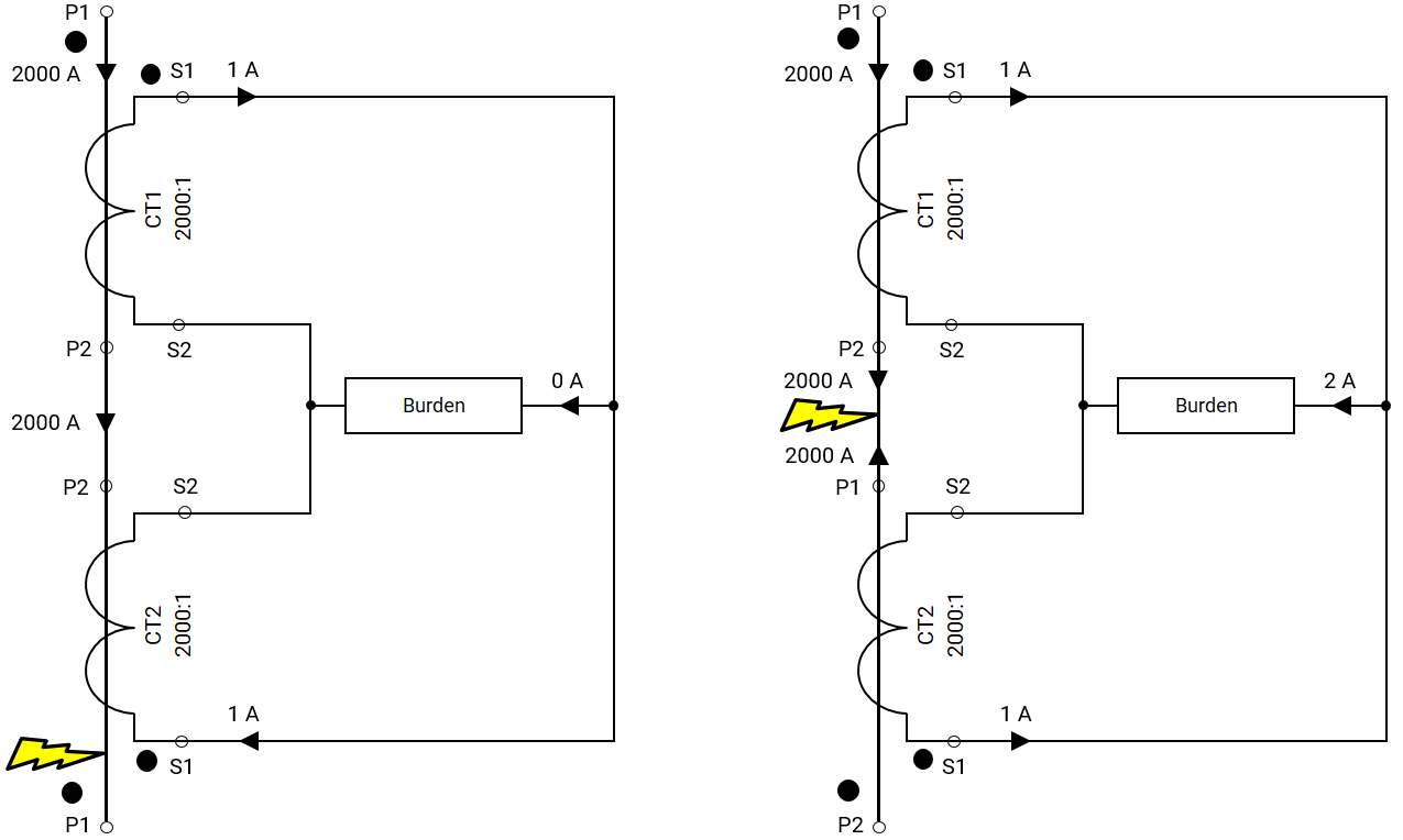
Connection of CT Secondary Windings
Assume that the two CTs have the same ratio of 2000:1 and that the primary current is 2000 A. The left-hand diagram shows primary and secondary instantaneous current flows for normal loads or a fault outside the zone of protection (the zone of protection is between the two CTs). The burden current becomes zero.
The diagram on the right shows primary and secondary instantaneous current flows for a fault inside the zone of protection.
In a healthy state, the secondary currents of current transformers (installed at the two ends of the busbar) are balanced, thus cancelling each other out. In the case of a fault on the busbar, the secondary currents are not equal but opposite, and thus a resultant current flows through the burden (relay) actuating the operation of the corresponding circuit breaker to isolate and clear the fault.
Related Online Engineering Courses
Introduction to Electrical Transformers
How Electrical Transformers Work
Electrical Transformer Health Assessment
Voltage, Current, and Resistance, Explained
Why Are Transformers Rated in VA not W?