


Introduction
There are various types of lead acid battery, these include gel cell, absorbed glass mat (AGM) and flooded. The original lead acid battery dates back to 1859 and although it has been considerably modernised since then, the theory remains the same. Absorbed glass mat batteries and gel cell batteries are often grouped together as valve regulated lead acid (VRLA) batteries.
Lead acid batteries do not have great energy to weight or energy to volume properties, but they remain in use because they are cheap to manufacture and have excellent power to weight properties. Lead acid batteries are employed extensively in the automobile industry because they are capable of discharging a large amount of current in a short period of time; this is precisely what is required to put a static internal combustion (IC) engine into motion (diesel or petrol fired etc.).
It is estimated that between 40-60% of the weight of an average lead acid battery is directly attributed to the lead plates (that is why the battery is so heavy).
How Lead Acid Batteries Work
Lead plates are suspended in electrolyte (water and sulphuric acid solution) within a plastic battery casing. Positive and negative plates are created with dissimilar coatings in order that current flows between them. As current flows between the plates due to chemical reaction, lead sulphate forms on both the positive and negative plates (lead sulphate appears as a yellow coating). As the lead sulphate increases, the voltage begins to decrease. The lead sulphate will crystallise upon the plates if a battery charger is not immediately connected and a charging current applied.
Enjoying this article? Then be sure to check out our Introduction to Batteries Video Course! The course has a quiz, handbook, and you will receive a certificate when you finish the course. Enjoy!
Lead-Acid Battery Types
Generally, there are two types of lead-acid storage batteries, based on their method of construction. These batteries are either called flooded (or vented) or sealed. Flooded and sealed batteries also differ in their operation. All lead-acid batteries produce hydrogen and oxygen gas (gassing) at the electrodes during charging through a process called electrolysis. These gases are allowed to escape a flooded cell, however, the sealed cell is constructed so that the gases are contained and recombined. It should be noted that hydrogen gas is explosive in air at only 4% by volume. Flooded and sealed lead-acid batteries are discussed in the following paragraphs.
Flooded Lead-Acid Batteries
Flooded cells are those where the electrodes/plates are immersed in electrolyte. Since gases created during charging are vented to the atmosphere, distilled water must be added occasionally to bring the electrolyte back to its required level. The most familiar example of a flooded lead-acid cell is the 12-V automobile battery.
Sealed Lead-Acid Batteries
These types of batteries confine the electrolyte, but have a vent or valve to allow gases to escape if internal pressure exceeds a certain threshold. During charging, a lead-acid battery generates oxygen gas at the positive electrode.
Sealed lead-acid batteries are designed so that the oxygen generated during charging is captured and recombined in the battery. This is called an oxygen recombination cycle and works well as long as the charge rate is not too high. Too high of a rate of charge may result in case rupture, thermal runaway, or internal mechanical damage.
The valve-regulated battery is the most common type of sealed battery. It was developed for stationary and telecommunication battery applications. These types of sealed batteries have a spring-controlled valve that vents gases at a predetermined pressure. Typical pressure thresholds are from 2 to 5 psig, depending on the battery design. Although the term "valve-regulated" is often used synonymously to describe sealed lead-acid batteries, not all sealed batteries are valve-regulated. Some battery designs employ replaceable vent plugs or other mechanisms to relieve excess pressure. Sealed batteries were developed to reduce the maintenance required for batteries in active service. Since electrolyte levels are preserved by trapping and recombining off-gasses, there should not be any need to add distilled water over the life of the battery. These batteries are often misnamed "maintenance free”. In fact, all maintenance practices applicable to unsealed type batteries are applicable to sealed type batteries. The only exception is that electrolyte levels cannot, and should not need to be, maintained.
Sealed type batteries are often avoided for backup power source applications for several reasons. One reason is that the state of charge of sealed type batteries cannot be ascertained by the usual specific gravity measurement. Reliable alternative methods to measure the state of charge for sealed type batteries are under development. A second reason is their sensitivity to high temperatures.
Operation and Construction
The following paragraphs describe the general operation and construction of lead-acid batteries.
Lead-Acid Battery Active Materials
The active materials in a battery are those that participate in the electrochemical charge/discharge reaction. These materials include the electrolyte and the positive and negative electrodes. As mentioned earlier, the electrolyte in a lead-acid battery is a dilute solution of sulfuric acid (H2SO4). The negative electrode of a fully charged battery is composed of sponge lead (Pb) and the positive electrode is composed of lead dioxide (PbO2).
Electrochemistry of the Lead-Acid Cell
All lead-acid batteries operate on the same fundamental reactions. As the battery discharges, the active materials in the electrodes (lead dioxide in the positive electrode and sponge lead in the negative electrode) react with sulfuric acid in the electrolyte to form lead sulphate and water. On recharge, the lead sulphate on both electrodes converts back to lead dioxide (positive) and sponge lead (negative), and the sulphate ions (SO42-) are driven back into the electrolyte solution to form sulfuric acid. The reactions involved in the cell follow.
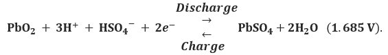
At the positive electrode
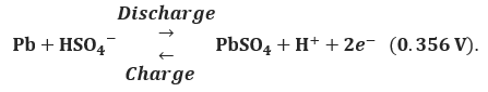
At the negative electrode
For the overall cell
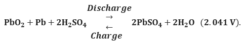
Therefore, the maximum open-circuit voltage that can be developed by a single lead-acid cell is 2.041 V.
Negative and Positive Plate Construction Methods
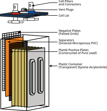
The simplest method for the construction of lead-acid battery electrodes is the Planté plate, named after the inventor of the lead-acid battery. A Planté plate is merely a flat plate composed of pure lead. Since the capacity of a lead-acid battery is proportional to the surface area of the electrodes that is exposed to the electrolyte, various schemes are employed to increase the surface area of the electrodes per unit volume or weight. Planté plates are grooved or perforated to increase their surface area. A typical Planté plate is shown in the image below.
The most commonly used method to increase surface area is to make the active material into a paste that acts like a sponge where the electrolyte fills all the pores. The paste, or active material, is mounted into a frame or grid structure that mechanically supports it and serves as the electrical conductor carrying the current during both the charge and discharge cycle. The most commonly used plate today is the pasted plate, also known as the flat plate. This grid structure is a lattice-work that resembles the cross section of a honeycomb, with the paste filling all of the rectangular windows on the structure. In the image below shows a typical construction of a pasted plate grid. The flat plate construction is used as the negative electrode plate in almost all cases, and serves as the positive plate in most standby applications.
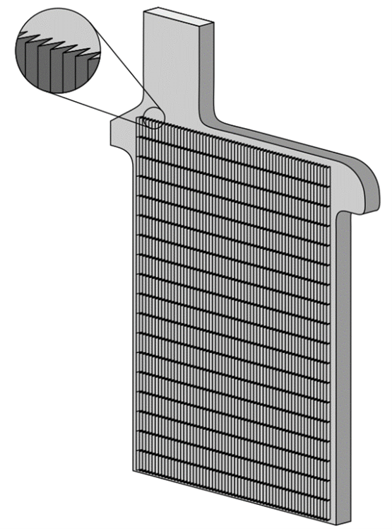
Typical Planté Plate
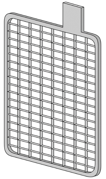
Typical Construction of a Pasted Plate Grid
Positive electrodes are usually of pasted plate or tubular construction. Tubular electrodes are popular positive plates for heavy cycling applications. This construction uses a frame structure consisting of a series of vertical spines connected to a common bus (busbar). The paste is held in micro-porous, non-conductive tubes which are placed over the individual spines. A simplified view of tubular plate construction is shown in the image below. Regardless of the plate type used, the capacity of any battery is increased by adding multiple plates in parallel.
Antimony/Calcium/Selenium/Tin Alloying
The grid structure in both pasted and tubular plate batteries is made from a lead alloy. A pure lead grid structure is not strong enough by itself to stand vertically while supporting the active material. Other metals in small quantities are alloyed with lead for added strength and improved electrical properties. The most commonly alloyed metals are antimony, calcium, tin, and selenium.
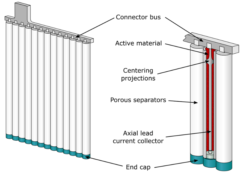
Typical Construction of a Tubular Plate
The two most common alloys used today to harden the grid are antimony and calcium. Batteries with these types of grids are sometimes called "lead-antimony" and "lead-calcium" batteries. Tin is added to lead-calcium grids to improve cyclability. The major differences between batteries with lead-antimony and lead-calcium grids are as follows:
- Lead-antimony batteries can be deep cycled more times than lead-calcium batteries.
- Flooded lead-antimony batteries require more frequent maintenance as they near end-of-life since they use an increasing amount of water and require periodic equalization charges.
- Lead-calcium batteries have lower self-discharge rates as shown in the image below and therefore, will draw less current while on float charge than lead-antimony batteries.
- Lead-calcium positive plates may grow in length and width because of grid oxidation at the grain boundaries. This oxidation is usually caused by long-term overcharging, which is common to UPS and other batteries on constant-float changing. Grids may grow in size sufficiently to cause buckling or rupture of their containers.
 .
.
Self-Discharge Rates of Three Grid Materials
Another type of grid alloy is lead-selenium. In reality, this battery is actually a low lead-antimony grid with a slight amount of selenium. Lead-selenium has characteristics that fall somewhere between lead-calcium and lead-antimony.
When pure lead is mixed with an alloy there may be undesirable characteristics introduced in the performance of the battery. Modern day battery manufacturers try to reduce the amount of antimony and calcium by introducing doping agents such as selenium, cadmium, tin, and arsenic. When batteries containing arsenic and antimony are charged (especially overcharged) the poisonous gases arsine (AsH3) and stibine (SbH3) may be released. This is discussed further in the paragraphs devoted to charging.
Specific Gravity
One of the key parameters of battery operation is the specific gravity of the electrolyte. Specific gravity is the ratio of the weight of a solution to the weight of an equal volume of water at a specified temperature. Specific gravity is used as an indicator of the state of charge of a cell or battery. However, specific gravity measurements cannot determine a battery's capacity. During discharge, the specific gravity decreases linearly with the ampere-hours discharged as indicated in the image below.
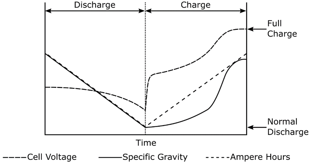
Changes in Voltage and Specific Gravity During Charge and Discharge
Therefore, during fully charged steady-state operation and on discharge, measurement of the specific gravity of the electrolyte provides an approximate indication of the state of charge of the cell. The downward sloping line for the specific gravity during discharge is approximated by the equation below:
Specific gravity=cell open circuit voltage-0.845.
Or
Cell open circuit voltage = specific gravity + 0.845.
The above equations permit electrical monitoring of approximate specific gravity on an occasional basis. As mentioned earlier, specific gravity measurements cannot be taken on sealed lead-acid batteries. Measurement of the cell open-circuit voltage has been used as an indicator of the state of charge of a sealed battery. More reliable methods for determining the state of charge of sealed batteries are under development.
The specific gravity decreases during the discharging of a battery to a value near that of pure water and it increases during a recharge. The battery is considered fully charged when specific gravity reaches its highest possible value.
Specific gravity does, of course, vary with temperature and the quantity of electrolyte in a cell. When the electrolyte is near the low-level mark, the specific gravity is higher than nominal and drops as water is added to the cell to bring the electrolyte to the full level. The volume of electrolyte expands as temperature rises and contracts as temperature drops, therefore affecting the density or specific gravity reading. As the volume of electrolyte expands, the readings are lowered and, conversely, specific gravity increases with colder temperatures.
The specific gravity for a given battery is determined by the application it will be used in, taking into account operating temperature and battery life. Typical specific gravities for certain applications are shown in Table 1.
Table 1. Specific gravities for flooded batteries.
| Specific gravities | Application |
| 1.300 | Heavily cycled batteries such as for electric vehicles (traction) |
| 1.260 | Automotive (SLI) |
| 1.250 | UPS—Standby with high momentary current discharge requirement |
| 1.215 | General applications such as power utility and telephone applications |
In the selection of a battery for a given application, some of the effects of high or low specific gravity to be considered are:
| Higher gravity | Lower gravity |
| More capacity | Less capacity |
| Shorter life | Longer life |
| Less space required | More space required |
| Higher momentary discharge rates | Lower momentary discharge rates |
| Less adaptable to "floating" operation | More adaptable to "floating" operation |
| More standing loss | Less standing loss |
A solution of higher specific gravity is heavier per unit volume than one of lower specific gravity. Therefore, the more concentrated electrolyte created during charging sinks to the bottom of the battery jar creating a gradient in specific gravity. The gassing that occurs on overcharge serves as a "mixer" and makes the specific gravity uniform throughout the cell. To avoid erroneous readings, specific gravity measurements should only be taken after an equalizing charge and subsequent float charge for at least 72 hours. The reader should seek additional guidance on specific gravity from ANSI/IEEE Std 450, IEEE Recommended Practice for Maintenance, Testing, and Replacement of Large Lead Storage Batteries for Generating Stations and Substations.
Effects of Discharge Rate and Temperature on Capacity and Life
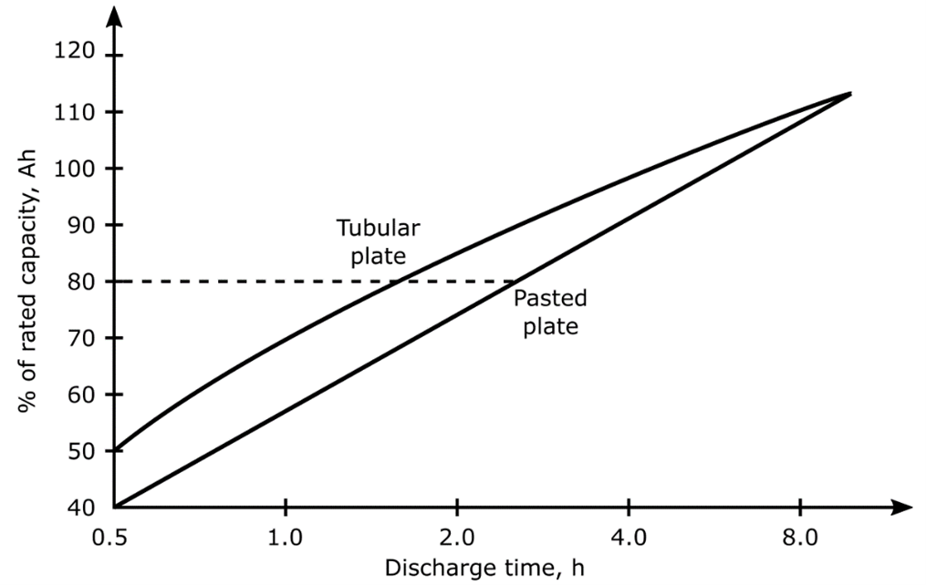
The rate at which a battery is discharged and its operating temperature have a profound effect on its capacity and life. An example of the effect of discharge rate on battery capacity is shown in the image below for traction batteries. This image shows that batteries discharged at a low rate will be able to deliver a higher capacity than those discharged at a high rate.
The depth of discharge also affects the life of a battery. As shown in the image below for a typical traction battery, discharges beyond about 80% of capacity can be expected to shorten battery life.
Colder operating temperatures will yield a little extra life, but also lower the capacity of lead acid cells. High temperatures yield higher capacity (see the image below) but have a detrimental effect on life.
Typical Effects of Discharge Rate on Battery Capacity
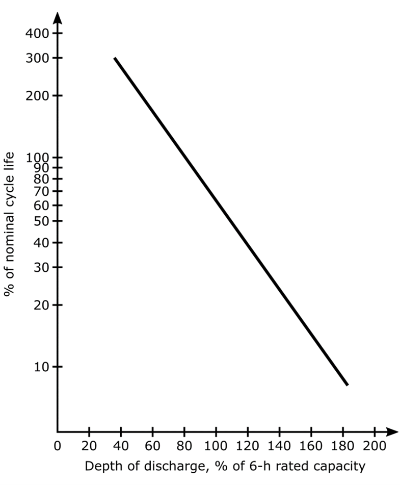
Typical Effects of Depth of Discharge on Traction Battery Life
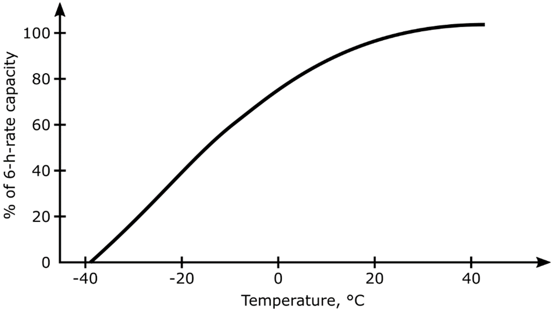
Typical Effects of Operating Temperatures on Traction Battery Capacity
Applications
There are numerous applications for the use of lead-acid storage batteries. They range from the extremely large battery systems used in load levelling by electrical utility companies to the relatively small batteries used in hand tools. Batteries may need to undergo deep and frequent cycling such as those used for electric vehicle power or they may remain on "float" as in an emergency lighting application and only rarely be discharged. Clearly, these applications cannot all use the same battery. Restraints on parameters such as operating temperature, desired capacity, voltage and power requirements, etc., affect the type of battery chosen.
All the above considerations are taken into account by determining the battery's duty cycle. The duty cycle is the required operating parameters of a cell or battery including factors such as charge and discharge rates, depth of discharge, cycle length, and length of time in the standby mode. The duty cycle must be known and included in the battery procurement specification. The duty cycle and battery chosen will also determine the type of charger used. More details on matching chargers to batteries and applications are included in later paragraphs. More information on duty cycles is included in the section entitled "Sizing and Selection”.
The major categories of lead-acid battery applications are starting, lighting, and ignition (SLI); industrial, including traction and stationary applications; and small portable equipment. A brief description of each type is included below along with example uses of each type.
Starting, Lighting, and Ignition
SLI batteries are used by most people every day and are produced in greater numbers than any other type of lead-acid storage battery. These are used to start automobiles and most other kinds of internal combustion engines. They are not suitable for deep discharge applications, but excel for uses needing a high current for a brief time. They are usually charged in a "partial float" manner, meaning that the battery only receives a float charge while the vehicle is running. A cutaway view of a typical SLI battery is shown in the image below. SLI batteries are usually of the flat pasted plate design.
.png)
Cutaway View of a Typical Battery Used For Starting, Lighting, and Ignition (SLI)
Industrial
Industrial batteries generally have the largest capacity of the three major categories of lead-acid batteries. Industrial batteries are used for vehicle traction and stationary applications.
Traction
Traction batteries are used to provide motive power for electric or hybrid vehicles. The major emphasis on traction battery design is the necessity of a high capacity to weight and volume ratio, since the vehicle must also carry its power source. Traction batteries are frequently deep cycled and require a fast-charging rate for use usually within 24 hours. Typical applications are motive power for fork lifts and electric carts. Traction batteries are usually of the tubular plate design, which performs more favorably during deep cycle operation.
Stationary
Stationary batteries come in a wide variety of designs for different applications. They are used for applications where power is necessary only on a standby or emergency basis. Stationary batteries are infrequently discharged. Stationary batteries remain on a continuous float charge so that they can be used on demand. The largest types of stationary batteries are those used for electrical load levelling. Load-levelling batteries store electrical energy for times of peak power demand and are taken off-line during times of low power demand. Stationary batteries are also used for backup emergency power, telecommunications equipment, and uninterruptible power supplies. Stationary batteries are manufactured in a variety of plate designs. An example of a stationary battery used for backup power is shown in the image below.
Typical Stationary Battery Used for Backup Power
Portable
Portable lead-acid batteries are usually of the sealed type constructed similarly to that depicted in the image below. Their operation cannot usually be described as cyclic or float, but is somewhere in-between. Batteries in this category may be frequently deep cycled or remain unused for a relatively long time. Typical applications are portable tools, toys, lighting and emergency lighting, radio equipment, and alarm systems. Most portable batteries may be recharged to 80–90% of their original capacity in less than an hour using a constant-voltage charger.

Components of Sealed Lead-Acid Cell
Sizing and Selection
Sizing and selection of lead-acid batteries should be performed according to ANSI/IEEE Std 485, IEEE Recommended Practice for Sizing Large Lead Storage Batteries for Generating Stations and Substations. As described earlier, the duty cycle is the most important criterion in battery sizing and selection. ANSI/IEEE Std 485 contains directions as well as a sample exercise for determining the duty cycle. A simple duty cycle diagram is shown in the image below.
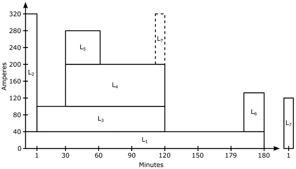
Diagram of a Duty Cycle
Each of the loads (designated by L1-6) requires a certain amperage for a specified time and duration. In the example duty cycle, a randomly occurring load (L7) is assumed to occur in the 120th minute. The placement of randomly occurring loads in the duty cycle is also covered in ANSI/IEEE Std 485.
Other selection factors recommended by ANSI/IEEE Std 485 are the following:
- Physical characteristics, such as size and weight of the cells, container material, vent caps, intercell connectors, and terminals
- Planned life of the installation and expected life of the cell design
- Frequency and depth of discharge
- Ambient temperature
- Maintenance requirements for the various cell designs
- Seismic characteristics of the cell design.
Maintenance
Proper maintenance will prolong the life of a battery and will aid in assuring that it is capable of satisfying its design requirements. A good battery maintenance program will serve as a valuable aid in determining the need for battery replacement. Battery maintenance should always be performed by trained personnel knowledgeable of batteries and the safety precautions involved.
Most of the following material concerns flooded, non-maintenance-free batteries. However, so called "maintenance-free" and valve-regulated batteries also require some maintenance. They do not require water addition or checking of specific gravity, but they may require periodic cleaning, monitoring of cell and battery total float voltage, load (capacity) testing, terminal resistance measurement, or cleaning and torquing of terminal bolts depending on the importance of the application.
General
In general, a good maintenance and inspection program should be based on relevant standards, such as ANSI/IEEE Std 450, IEEE Recommended Practice for Maintenance, Testing, and Replacement of Large Lead Storage Batteries for Generating Stations and Substations. Some of the recommended practices from these and other references are presented in the following paragraphs.
Flooded lead-acid batteries can function for 10 years or longer if properly maintained. The six general rules of proper maintenance are:
- Match the charger to the battery requirements.
- Avoid over discharging the battery.
- Maintain the electrolyte at the appropriate level (add water as required).
- Keep the battery clean.
- Avoid overheating the battery.
- Provide an equalizing charge periodically to weak batteries/cells.
Matching the Charger to Battery Requirements
Poor charging practice is responsible for shortening the life of a battery more than any other cause. Charging may be accomplished by various methods, but the objective of driving current through the battery in the opposite direction of discharge remains the same. The most important aspect of charging is matching the charger to the battery application. When choosing a charger, it is necessary to consider the type of battery, the way in which the battery will be discharged, the time available for charge, the temperature extremes the battery will experience, and the number of cells in the battery (output voltage). It is important to consult the battery manufacturer at the time of purchase to determine the appropriate charging method.
In general, lead-acid batteries may be recharged at any rate that does not produce excessive gassing, overcharge, or high temperatures. Discharged batteries may be recharged at a high current initially. However, once the battery approaches its full charge the current must be decreased to reduce gassing and excessive overcharging.
A wide variety of schemes exist for charging lead-acid batteries. Although a complete discussion of various charging techniques is beyond the scope of this course, a general description of the more common methods follows.
Constant-Voltage Charging
Constant-voltage (often called constant-potential) chargers maintain nearly the same voltage input to the battery throughout the charging process, regardless of the battery's state of charge. Constant-voltage chargers provide a high initial current to the battery because of the greater potential difference between the battery and charger. A constant-voltage charger may return as much as 70% of the previous discharge in the first 30 minutes. This proves useful in many battery applications involving multiple discharge scenarios. As the battery charges its voltage increases quickly. This reduces the potential that has been driving the current, with a corresponding rapid decrease in charge current as depicted in the image below. As a result, even though the battery reaches partial charge quickly, obtaining a full charge requires prolonged charging.
Given this behavior, constant-voltage chargers are frequently found in applications that normally allow extended charging periods to attain full charge. Constant-voltage chargers should not be used where there is frequent cycling of the battery. Repeated discharges without returning the cell to its full charge will eventually decrease the battery capacity and may damage individual cells.
Constant-voltage chargers are most often used in two very different modes: as a fast charger to restore a high percentage of charge in a short time or as a float charger to minimize the effects of overcharge on batteries having infrequent discharges as described below.
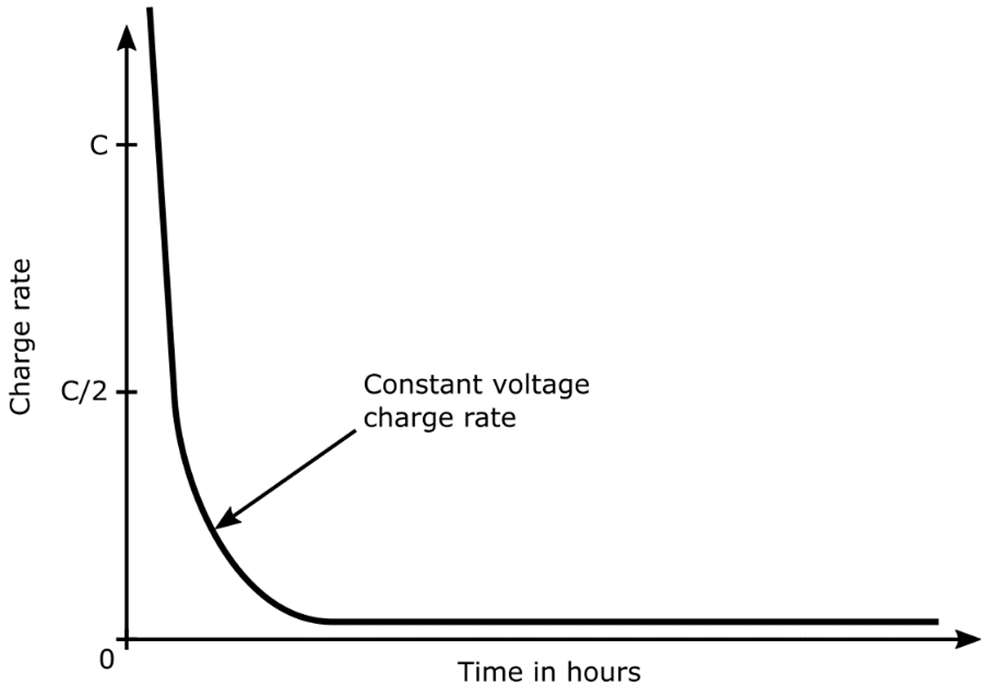
Charge Rate versus Time for a Typical Constant-Voltage Charger
Float Charging
Float charging is most commonly used for backup and emergency power applications where the discharge of the battery is infrequent. During float charging the charger, battery, and load are connected in parallel. The charger operates off the normal power supply which provides current to the load during operation. In the event of normal power supply failure, the battery provides backup power until the normal power supply is restored. Since most equipment requires alternating current, a rectifier circuit converts alternating current to direct current and is usually added between the battery and the load. Float chargers are typically constant-voltage chargers that operate at a low voltage. Operating the charger at a low voltage, usually less than about 2.4 V per cell, keeps the charging current low and thus minimizes the damaging effects of high-current overcharging.
For valve-regulated batteries, an important consideration when float charging is the possible occurrence of a phenomena called "thermal runaway". The best way of preventing thermal runaway is through the use of a temperature-compensated battery charger. A temperature-compensated charger adjusts the float voltage based upon battery temperature. Temperature-compensated chargers will increase the reliability and prolong the life of the battery/charger system. They are especially useful for batteries located in areas where temperatures may be significantly above ambient conditions.
Constant-Current Charging
Constant-current charging simply means that the charger supplies a relatively uniform current, regardless of the battery state of charge or temperature. Constant-current charging helps eliminate imbalances of cells and batteries connected in series. Single-rate, constant-current chargers are most appropriate for cyclic operation where a battery is often required to obtain a full charge overnight. At these high rates of charge there will be some venting of gases. Positive grid oxidation will occur at elevated temperatures or extended overcharge times. Normally the user of a cyclic application is instructed to remove the battery from a single-rate, constant-current charger within a period of time that permits full charge yet prevents excessive grid oxidation.
Another type of constant-current charger is the split-rate charger. A split-rate charger applies a high initial current to the cell and then switches to a low rate based on time of charge, voltage, or both. The choice of switching method and switch point may be affected by the relative priority of minimizing venting (early switching) versus maintaining good cell balance (later switching). In some split rate chargers, the charger will alternate between the high and low rate as the battery approaches full charge. Split-rate chargers are useful when the discharge cannot be classified as float or cyclic, but lies somewhere between the two applications.
Trickle Charging
A trickle charge is a continuous constant-current charge at a low (about C/100) rate which is used to maintain the battery in a fully charged condition. Trickle charging is used to recharge a battery for losses from self-discharge as well as to restore the energy discharged during intermittent use of the battery. This method is typically used for SLI and similar type batteries when the battery is removed from the vehicle or its regular source of charging. Trickle charging is also used widely for portable tools and equipment such as flashlights and battery powered screwdrivers.
Avoiding Overdischarge
In order to obtain maximum life from lead-acid batteries, they should be disconnected from the load once they have discharged their full capacity. The cut-off voltage of a lead-acid cell is usually around 1.75 V. However, the cut-off voltage is very sensitive to operating temperature and discharge rate. Like batteries discharged at a high rate will have a lower cut-off voltage than those discharged at a low rate. Greater capacities are obtained at higher temperatures and low discharge rates. The manufacturer should specify cut-off voltages for various operating temperatures and discharge rates. Overdischarge may cause difficulties in recharging the cell by increasing the battery's internal resistance. Also, overdischarging may cause lead to be precipitated in the separator and cause a short in the cell or between cells.
Maintaining Electrolyte Levels
During normal operation, water is lost from a flooded lead-acid battery as a result of evaporation and electrolysis into hydrogen and oxygen, which escape into the atmosphere. One Faraday of overcharge will result in a loss of about 18 g of water. Evaporation is a relatively small part of the loss except in very hot, dry climates. With a fully charged battery, electrolysis consumes water at a rate of 0.336 cm3 per ampere-hour overcharge. A 500-Ah battery overcharged 10% can thus lose 16.8 cm3, or about 0.3%, of its water each cycle. It is important that the electrolyte be maintained at the proper level in the battery. The electrolyte not only serves as the ionic conductor, but is a major factor in the transfer of heat from the plates. If the electrolyte is below the plate level, then an area of the plate is not electrochemically efficient; this causes a concentration of heat in other parts of the battery. Periodic checking of water consumption can also serve as a rough check on charging efficiency and may warn when adjustment of the charger is required.
Since replacing water can be a major maintenance cost, water loss can be reduced by controlling the amount of overcharge and by using hydrogen and oxygen recombining devices in each cell where possible. Addition of water is best accomplished after recharge and before an equalization charge. Water is added at the end of the charge to reach the high-level line. Gassing during overcharge will stir the water into the acid uniformly. In freezing weather, water should not be added without mixing as it may freeze before gassing occurs. Only distilled water should be added to batteries. Although demineralized or tap water may be approved for some batteries, the low cost of distilled water makes it the best choice. Automatic watering devices and reliability testing can reduce maintenance labor costs further. Overfilling must be avoided because the resultant overflow of acid electrolyte will cause tray corrosion, ground paths, and loss of cell capacity. Although distilled water is no longer specified by most battery manufacturers, good quality water, low in minerals and heavy metal ions such as iron, will help prolong battery life.
Cleaning
Keeping the battery clean will minimize corrosion of cell post connectors and steel trays and avoid expensive repairs. Batteries commonly pick up dry dirt which can be readily blown off or brushed away. This dirt should be removed before moisture makes it a conductor of stray currents. The top of the battery can become wet with electrolyte any time a cell is overfilled. The acid in this electrolyte does not evaporate and should be neutralized by washing the battery with a solution of baking soda and hot water, approximately 1 kg of baking soda to 4 L of water. After application of such a solution, the area should be rinsed thoroughly with water.
Avoiding High Temperatures
One of the most detrimental conditions for a battery is high temperature, particularly above 55ºC, because the rates of corrosion, solubility of metal components, and self-discharge increase with increasing temperature. High operating temperature during cycle service requires higher charge input to restore discharge capacity and self-discharge losses. More of the charge input is consumed by the electrolysis reaction because of the reduction in the gassing voltage at the higher temperature. While 10% overcharge per cycle maintains the state of charge at 25 to 35ºC, 35 to 40% overcharge may be required to maintain state of charge at the higher (60 to 70ºC) operating temperatures. On float service, float currents increase at the higher temperatures, resulting in reduced life. Eleven days float at 75ºC is equivalent in life to 365 days at 25ºC. Batteries intended for high-temperature applications should use a lower initial specific gravity electrolyte than those intended for use at normal temperatures. Manufacturers should be consulted on acceptable temperature ranges for operation of their batteries and on the associated effects of temperature. Nickel-cadmium batteries may be more suitable for higher-temperature applications.
Supplying an Equalizing Charge
Often a multi-cell battery will have one or more cells at a significantly lower voltage than other cells in the battery. When the battery is discharged the cells with lower voltage may become overdischarged. As noted earlier, overdischarge may cause enough damage to a cell that it needs to be replaced. When a difference exists between the potentials of cells in the same battery, an equalizing charge is applied to bring them up to an equal potential to the other cells. Criteria for applying an equalizing charge may be found in ANSI/IEEE 450, IEEE Recommended Practice for Maintenance, Testing, and Replacement of Large Lead Storage Batteries for Generating Stations and Substations.
Safety Precautions
Safety problems associated with lead-acid batteries include spills of sulfuric acid, potential explosions from the generation of hydrogen and oxygen, and the generation of toxic gases such as arsine and stibine. All these problems can be satisfactorily handled with proper precautions. NFPA 70, National Electrical Code, provides guidance on battery room ventilation. Wearing of face shields and plastic or rubber aprons and gloves when handling acid is recommended to avoid chemical burns from sulfuric acid. Flush immediately and thoroughly with clean water if acid gets into the eyes, skin, or clothing and obtain medical attention when eyes are affected. A bicarbonate of soda solution is commonly used to neutralize any acid accidentally spilled. After neutralization the area should be rinsed with clear water.
Precautions must be routinely practiced to prevent explosions from ignition of the flammable gas mixture of hydrogen and oxygen formed during overcharge of lead-acid cells. The maximum rate of formation is 0.42 L of hydrogen and 0.21 L of oxygen per ampere-hour a overcharge at standard temperature and pressure. The gas mixture is explosive when hydrogen in air exceeds 4% by volume. A standard practice is to set warning devices to ring alarms at 20 to 25% of this lower explosive limit (LEL). Hydrogen detectors are available commercially for this purpose.
With good air circulation around a battery, hydrogen accumulation is normally not a problem. However, if relatively large batteries are confined in small rooms, exhaust fans should be installed to vent the room constantly or to be turned on automatically when hydrogen accumulation exceeds 20% of the lower explosive limit. Battery boxes should also be vented to the atmosphere. Sparks or flame can ignite these hydrogen mixtures above the LEL. To prevent ignition, electrical sources of arcs, sparks, or flame should be mounted in explosion-proof metal boxes. Flooded batteries can similarly be equipped with flame arrestors in the vents to prevent outside sparks from igniting explosive gases inside the cell cases. It is mandatory to refrain from smoking, using open flames, or creating sparks in the vicinity of the battery. A considerable number of the reported explosions of batteries come from uncontrolled charging in non-automotive applications. Often batteries will be charged, off the vehicle, for long periods of time with an unregulated charger. In spite of the fact that the charge currents can be low, considerable volumes of gas can accumulate. When the battery is then moved, this gas vents, and if a spark is present, explosions have been known to occur. The introduction of calcium alloy grids has minimized this problem, but the possibility of explosion is still present.
Some types of batteries can release small quantities of the toxic gases, stibine and arsine. These batteries have positive or negative plates that contain small quantities of the metals antimony and arsenic in the grid alloy to harden the grid and to reduce the rate of corrosion of the grid during cycling. Arsine (AsH3) and stibine (SbH3) are formed when the arsenic or antimony alloy material comes into contact with hydrogen, generated during overcharge of the battery. They are extremely dangerous and can cause serious illness and death. Ventilation of the battery area is very important. Indications are that ventilation designed to maintain hydrogen below 20% LEL (approximately 1% hydrogen) will also maintain stibine and arsine below their toxic limits.
The following summary of safety precautions will aid in preventing personal injury and/or damage to property:
- Follow applicable site and area safety rules for work on batteries.
- Obtain an approved Work Clearance permit per the Site Safety Manual before initiating any work on batteries.
- The use of personal protection articles such as acid-resistant gloves, apron, face shield, and goggles is required.
- Electrolyte is extremely corrosive and extreme care is required during handling.
- Use only non-conductive/insulated/non-sparking tools in the battery room.
- Do not smoke or use open flames, do not cause arcing in the vicinity of the battery.
- All metal objects such as jewelry (rings, bracelets, necklaces) must be removed before working on batteries.
- Neutralize static build up just before working on batteries by having personnel contact the nearest effectively grounded surface.
- Ensure the entrance and exit from the battery area is unobstructed.
- Verify availability of currently inspected and operable (portable or stationary) water facilities for rinsing eyes and skin in case of an acid spill.
- A Radiation Work Permit is required for all work in a radiologically controlled area.
- For safety reasons, a person shall not work alone. At least two persons (Two Man Rule) must always be present when working on electrical power systems.
Testing
Batteries should be tested at regular intervals to (a) determine whether the battery meets its specification or the manufacturer's rating, or both; (b) periodically determine whether the performance of the battery, as found, is within acceptable limits, and (c) if required, determine whether the battery as found meets the design requirements of the system to which it is connected. The schedule and procedure for battery capacity tests should be performed according to the requirements of ANSI/IEEE Std 450, IEEE Recommended Practice for Maintenance, Testing, and Replacement of Large Lead Storage Batteries for Generating Stations and Substations.
For an acceptance or performance test, use the following equation to determine battery capacity:
% capacity at 25ºC (77ºF) = Ta/Ts • 100,
where
Ta = actual time of test to specified terminal voltage
Ts = rated time to specified terminal voltage.
ANSI/IEEE Std 450 recommends replacement of a battery if its capacity as determined from the equation above is less than 80% manufacturer's rating. A capacity of 80% shows that the battery rate of deterioration is increasing even if there is ample capacity to meet load requirements. If individual cells are required to be replaced, they should be compatible with existing cells and tested prior to installation. It is recommended that when one or more cells/jars are replaced the entire battery string be replaced in order to prevent large differences in cell impedance. If uncorrected, this may result in unequal charging of the battery string.
Storage, Transportation, and Disposal
Storage
The storage of lead-acid batteries is fairly straightforward. Lead-acid batteries must be stored in the open-circuit condition with the terminals insulated. Long periods of storage at even low drain rates may result in permanent damage. Batteries should be stored in cool, dry, environments in their upright position. To maximize the length a battery may be stored it should be completely charged in the beginning. Batteries that will be stored for extended periods should undergo regular open-cell voltage (OCV) checks and be recharged as necessary or at regularly scheduled intervals.
An important consideration during storage is a damaging process called sulfation. As cells sit in storage and self-discharge, the active materials of the electrodes convert to lead sulphate just as they do in other discharges. But, in self discharge the lead sulphate forms as larger crystals that have the effect of insulating the particles of the active material, either from each other or the grid. Since lead sulphate occupies more space than sponge lead, the negative plate expands in volume. If the cell is allowed to over discharge, the lead sulphate may expand to the point where it separates from the sponge lead and falls to the bottom of the jar as sediment. The overall effect is a loss of capacity and greater internal resistance. Sulphating is normally reversible for lead sulphate still attached to the negative plate by charging with a low current until the lead sulphate is converted back into sponge lead.
Transportation
Lead-acid batteries are regulated as a hazardous material by many shipping companies and regulatory bodies. Under certain conditions a shipper may be excluded from these requirements if the batteries and packing methods meet stringent requirements.
Disposal
Disposal of lead-acid batteries should be performed according to all federal, state, and local regulations. Lead-acid batteries should be reclaimed to avoid the regulatory requirements for hazardous waste treatment and disposal. Reclamation is required by law in some countries.
3D Model Components
This 3D model shows all major components associated with a typical flooded lead acid battery, these include:
- Tapered Terminal Posts
- Vent and Fill Plugs
- Through Partition Conductor
- Positive Plates (Lead Dioxide)
- Insulator
- Negative Plate (Lead)
- Plate Rests
- Sediment Space
- Electrolyte
Related Online Engineering Courses
How Battery Energy Storage Systems (BESS) Work
Additional Resources
https://en.wikipedia.org/wiki/Lead%E2%80%93acid_battery
https://batteryuniversity.com/learn/article/lead_based_batteries