


What are gear pumps?
A positive displacement pump (‘displacement pump’, ‘PD Pump’) uses mechanical action to physically compress a fluid; unlike a centrifugal pump which converts velocity to pressure.
There are two displacement pump types, rotary and reciprocating. A gear pump is a type of rotary displacement pump. Reciprocating displacement pumps are the other type of displacement pump; they move linearly and require suction and discharge valves to operate. Displacement pumps are generally used for lower flow and higher-pressure applications, but this is a very rough generalisation.
Invented in the early 17th century by Johannes Kepler, gear pumps are often used for hydraulic power applications as well as for high viscosity (thick fluid) applications. Like all positive displacement pumps, they can pump air, and are thus self-priming.
Whilst several gear pump designs exist, there are two main designs. One design uses two identical gears that engage with each other; this type is called an external gear pump. The second design has one gear placed within another; this type is called an internal gear pump.
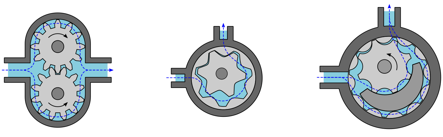
External (left) and Internal (centre and right) Gear Pump Designs
Fluids discharged from a gear pump generally flow with low pressure pulsations which results in a ‘smooth’ and constant flow. The flow rate through the pump directly correlates with the speed at which the gears rotate, which makes the gear pump a good choice of pump for metering applications (where the amount of flow needs to be measured accurately).
Gear pumps are usually electrically driven using an electric motor, but they may also be hydraulically or mechanically driven, depending upon the design and application. For example, many tractors use gear pumps for on-board hydraulic systems (raising and lowering a plough etc.), and the pump is connected mechanically to the tractor’s engine.
A gear pump’s speed of rotation and tight mechanical clearances minimise the amount of fluid flowing in the wrong direction (leakage); reduced leakage leads to higher pump efficiency.
Useful Knowledge – the fluid or material being pumped by a pump is referred to as ‘pumpage’. Pumpage may include solids, liquids, vapours, or gases, depending upon the pump design (screw pumps can pump nuts and bolts!).
Gear Pump Gears
Gear pump gears are often of the spur gear type, although gear pumps that use helical or herringbone gears are not uncommon. Helical and herringbone gears offer a smoother flow rate (lower pressure pulsations) than spur gears; they are also favoured for higher capacity/flow applications.

Gear Pump Gear Types
Enjoying this article? Then be sure to check out our Engineering Video Courses! Each course has a quiz, handbook, and you will receive a certificate when you finish the course. Enjoy!
External Gear Pumps
An external gear pump consists of a suction port, discharge port, gears, bearings, and a casing.
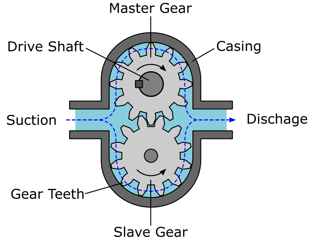
External Gear Pump Components
Gears in an external gear pump are installed parallel to each other. A shaft is installed through the centre axis of each gear and bearings hold each shaft in position. Both gears are classified as external gears because the gear teeth are located on the external surface of each gear. Typically, one gear is a driven gear (‘master’, ‘leader’) whilst the other is an idler gear (‘slave’, ‘follower’). Idler gears rotate only if their associated driven gear rotates. A casing with two penetrations surrounds the gears, these penetrations form the suction and discharge ports.

External Gear Pump Animation
Another external gear pump design utilises gears that are both driven by timing gears, but this design is more complicated, more expensive, and consequently less common. It does however have the advantage that the gears do not contact with each other, which means fluids with lower lubrication qualities (low lubricity) can be pumped.
Internal Gear Pumps
Internal gear pumps operate on the same theory as external gear pumps, but internal gear pumps have one gear installed within another. Unlike the gears in an external gear pump, the two mating gears are not the same size. The smaller inner gear is called the rotor and the larger outer gear the idler.

Internal Gear Pump Animation
Internal gear pumps have gear teeth on the internal surfaces of the idler gear so that they can interact with the rotor’s external gear teeth. The two sets of gears (rotor and idler) interlock/mesh with each other in the same manner as those in an external gear pump.
How Do Gear Pumps Work?
Gear pumps trap fluid on the suction side and discharge it at a higher pressure on the discharge side. The operating principle for an external gear pump is much the same as for an internal gear pump; both operating principles will be discussed separately for clarity.
How External Gear Pumps Work
Fluid enters the pump on the suction side. As the gears on the suction side rotate, the volumetric space between their gear teeth increases. Fluid enters the space/cavities between the teeth due to the negative suction pressure within the cavities. As the gears rotate further, fluid within the cavities becomes trapped between the gears and casing.
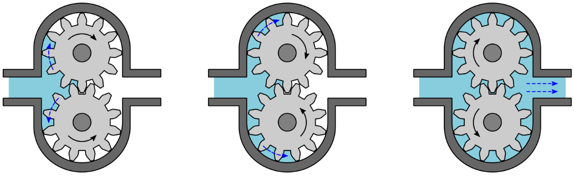
External Gear Pump Operation
After further rotation, the gears approach the discharge side. The gap between the gears and casing increases and the fluid escapes from the cavities. Further rotation of the gears leads to them meshing (interlocking), which leads to any remaining fluid within the cavities being ‘squeezed’ out. Thus, when the gears begin to separate again on the suction side, fluid can enter the vacant cavities, and the process can be repeated.
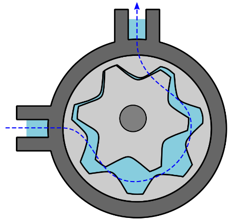
How Internal Gear Pumps Work
The drive mechanism (electric motor etc.) provides rotary motion to the rotor gear (the internal gear). As the rotor gear rotates, it causes the idler gear (external gear) to rotate also. Fluid enters on the suction side of the pump and flows into the cavities between the rotor and idler. A stationary crescent seal separates the two gears as they continue their rotation. Fluid is trapped in the cavities between the rotor gear and inner crescent surface, and between the idler gear and outer crescent surface. Further rotation of the gears brings the gear teeth from both gears closer together. As the gears begin to mesh, fluid is forced out of the cavities and is discharged from the pump; the process then repeats.
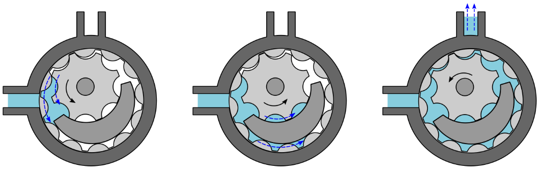
Internal Gear Pump Operation (with crescent)
Alternative internal gear pump designs use no crescent seal, but the working principle is much the same as for an internal gear pump with a crescent seal.
Internal Gear Pump Operation (without crescent)
Gear Pump Applications
Gear pumps are well suited for high-viscosity (thick) fluids with a low number of suspended solids. High viscosity fluids include substances such as paints and soaps etc. Because gear pumps have tight mechanical clearances, suspended solids within a fluid can cause abrasion of a gear pump’s parts, which leads to a reduction in pump efficiency and a reduced pump service life.
Typical gear pump applications include:
- Automotive fuels and oils.
- Hydraulic oils.
- Alcohol and solvents.
- Small-scale circulation of hot oil.
- Paints, resins, and polymers.
- Liquid soap.
- Edible foods such as corn syrup, animal feeds, and peanut butter.
Operating Characteristics
To enhance the operation of a gear pump, it’s important to reduce friction between its parts. Friction leads to heat, which will cause a gear pump’s components to physically expand. Gear pumps have tight mechanical clearances, particularly external gear pumps, thus any thermal expansion can cause damage to the pump. For example, gear teeth could become misaligned, which would lead to wear, leakage, and a consequent reduction in efficiency. In extreme cases, a severely misaligned gear pump may seize (no longer be able to rotate).
Typically, the fluid being pumped serves to lubricate the pump’s internal components. For this reason, most gear pumps are not well suited for dry operation (no fluid flow) over prolonged periods.
Gear pumps are more efficient when operating at their maximum design speed; lower revolutions per minute (rpm) will lead to lower pump efficiencies.
General Gear Pump Advantages
Gear pumps in general are useful due to their compact size and simplistic design. Because they have a low number of moving parts, they are more reliable than other, more complex, pump designs. They are often self-lubricating because the fluid they pump also lubricates the pump’s internal parts. Most gear pumps should not be operated dry for extended periods, as this will most likely lead to damage of the pump components due to friction/heat.
General Gear Pump Disadvantages
Due to the tight clearances that are necessary by their design (particularly for external gear pumps), gear pumps are susceptible to wear. As their parts wear/degrade, leakage occurs, and the pump’s efficiency reduces. If a gear pump must be used with abrasive solids (ill advised), the pressure should be low, the flow high, and the operating speed low.
As with all positive displacement pump designs, pressure relief devices should be installed to protect the pump and downstream components.
External Gear Pump Advantages and Disadvantages
An external gear pump can operate at higher pressures than some other pump types and often provides a more compact and less expensive design. External gear pumps work well at low to medium temperatures, whilst retaining a relatively high flow rate. The external gear pump design requires tight internal clearances, which make it ideal for batch applications, as it has a precise flow rate; it is also able to handle lower viscosity fluids as there is little leakage due to the tight clearances between parts. However, due to the tight clearances between its moving parts, an external gear pump often has a higher wear rate compared to other pump types.
Internal Gear Pump Advantages and Disadvantages
The internal gear pump works best under moderate pressure. It’s typically bulkier and more expensive than its external counterpart. Yet, it has several advantages over an external gear pump:
- It has a greater suction capability, so it is better suited for handling higher viscosity fluids.
- It is more robust because it has more relaxed mechanical clearances.
- Relaxed mechanical clearances allow it to better handle higher fluid temperatures (more room for thermal expansion of parts), which make it a good choice of pump for high temperature systems e.g. thermal oil.
Internal gear pumps are capable of bi-directional fluid flow (flow in two directions). This makes them useful if a single pump is required for a dual purpose e.g. filling and emptying a vessel.
Whilst it is ill advised to use any gear pump with abrasive substances or solids, internal gear pumps are better suited for this type of operation than external gear pumps, this is due to their relaxed mechanical tolerances. However, internal gear pumps are less able to handle lower viscosity fluids because the leakage rate is comparatively high (relaxed tolerances lead to higher leakage rates, especially for lower (thinner) viscosity fluids).
Related Online Engineering Courses
Introduction to Centrifugal Pumps
How Hand Pumps Work (hydraulic water pump)
How Multistage Centrifugal Pumps Work
Eductors, Ejectors, Venturi Pumps and Jet Pumps Explained
Additional Resources
https://kammash.com/learn-gear-pumps-characteristics-and-applications/