


Introduction
Closed-impellers are also referred to as 'enclosed impellers'. This type of impeller has both a front and back shroud; the impeller vanes are sandwiched between the two shrouds. Closed-impellers are installed on radial flow centrifugal pumps and can be either single inlet, or double inlet.
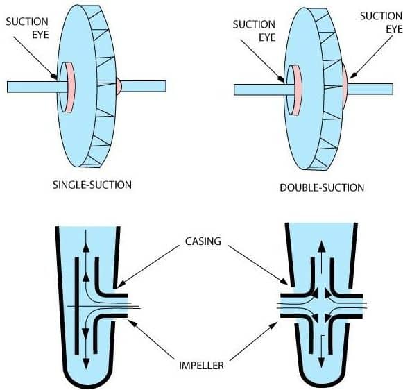
Single and Double Inlet Impellers
Closed-impellers are ideally suited for pumping liquids with a low amount of suspended bodies and a low viscosity (low resistance to flow). They can be used to pump liquids with a high amount of suspended solids, but the wear rate (rate the impeller erodes) will be high.
Closed-impellers are the most efficient type of radial flow impeller, as all flow is directed through the channels between the impeller vanes.
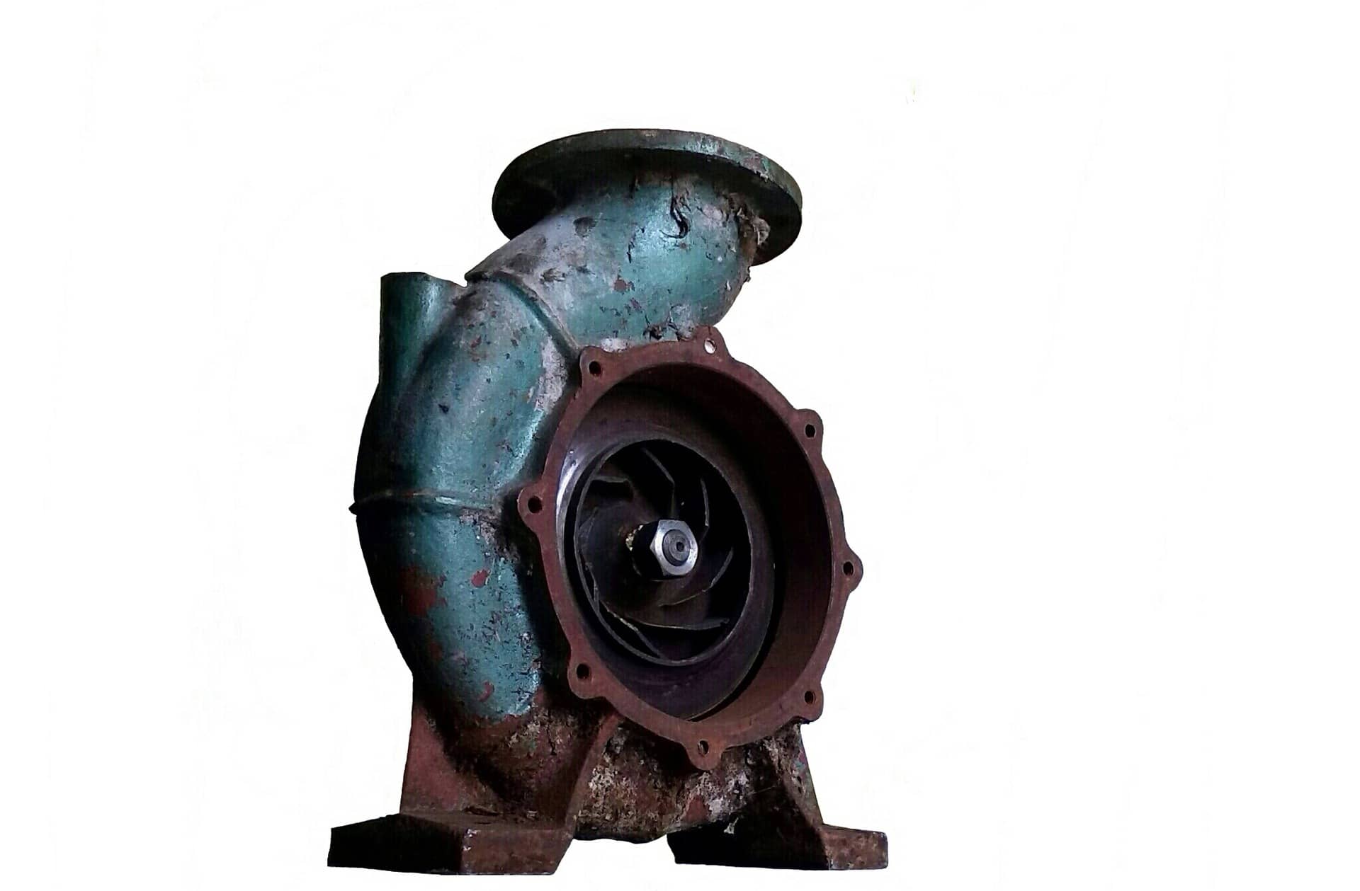
Radial Flow Centrifugal Pump
Compared to semi-open and open type impellers, the closed-impeller is the strongest, as the two shrouds increase the structural strength of the impeller.
Axial and radial thrusts created by closed impellers are not considerably high, which gives more flexibility when selecting bearings.

Axial and Radial Thrust
Typical applications for closed-impellers include fresh water and salt water systems.
Enjoying this article? Then be sure to check out our Centrifugal Pump Video Course! The course has a quiz, handbook, and you will receive a certificate when you finish the course. Enjoy!
How Impellers Work
The below video is an extract from our Introduction to Centrifugal Pumps Online Video Course.
Bernoulli's principle states that if a steady flow is exposed to a change in area, then the pressure and velocity will change correspondingly.
Example 1
If a pipe diameter increases, the pressure will increase, but the velocity will decrease.
Example 2
If a pipe diameter decreases, the pressure will decrease, but the velocity will increase.
Impellers are designed based upon Bernoulli's principle and the relationships between area, pressure and velocity.
Flow through the impeller vanes is radial. The impeller creates a negative pressure at the impeller eye (centre of the impeller) and this negative pressure draws liquid into the impeller. The liquid is thrown outwards radially due to the centrifugal force imparted onto it from the impeller. As the liquid flows through the vanes, the flow path area increases and there is a velocity decrease and a pressure increase.

Semi-Open Impeller
Notice on the above image that the distance between the channels (area between vanes) gradually increases as the vanes stretch towards the outer periphery. This gradual increase in area gives a gradual decrease in velocity and increase in pressure. The purpose of a volute casing and diffuser is to continue this velocity to pressure change in order to maximize the pressure and reduce the velocity as much as possible.
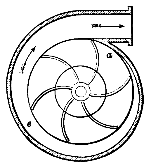
Impeller Surrounded by Volute Casing
Related Online Engineering Courses
Introduction to Centrifugal Pumps
How Multistage Centrifugal Pumps Work
Additional Resources
https://pumpbiz.com/blog/cat/pump-mentenance/post/right-centrifugal-pump-impeller-three-type