
_0.png)

Introduction
Cyclonic separation is a means of separating different liquid phases (different liquid densities), or, separating particles from a gas stream. Cyclone separators often form part of a pre-cleaning stage prior to a gas or liquid being discharged. This article focuses on the gas cyclone separator.
Cyclone Separators
What’s in a Name?
A cyclone separator has several colloquial names. These names include ‘dust separator’, ‘dust collector’, ‘dust extractor’, ‘cyclone extractor’ and ‘cyclone separator’. Generally, smaller units are referred to as ‘dust’ separators or extractors, whilst large scale industrial separators are referred to as ‘cyclone separators’.
Gas Cyclone and Hydrocyclone
There are two main designs of cyclone separator, these are the gas cyclone and hydrocyclone.
Gas cyclones are used to remove entrained particles from a gas stream.
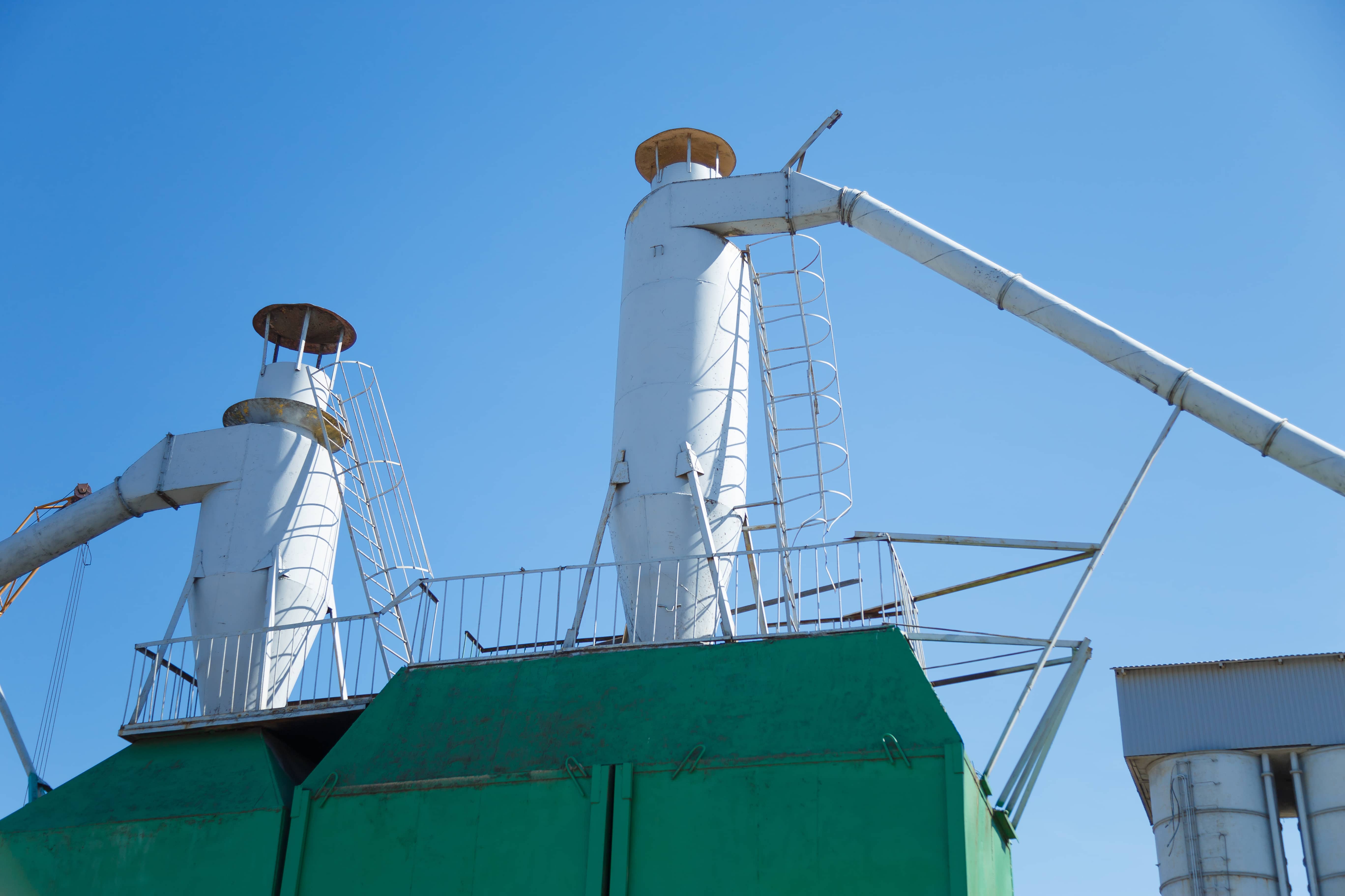
Typical Gas Cyclone Installation
Hydrocyclones are used for separating fluids of different densities.
Cyclone separators can be installed as single units, or in multiples, known as multi-cyclones. It is also possible to install cyclones in series, or, in parallel.
Separators can be installed with a horizontal or vertical orientation.
Enjoying this article? Then be sure to check out our Engineering Video Courses. Each course has a quiz, handbook, and you will receive a certificate when you finish the course. Enjoy!
Gas Cyclone Separators
Gas cyclone separators are grouped into two main categories, reverse-flow and axial-flow.
Reverse flow cyclone separators are cone shaped. Gas enters the top of the separator body, flows downwards, then flows back upwards and is discharged.
_0.png)
Reverse Flow Gas Cyclone Separator
Various reverse flow cyclone separator designs exist. Below is another variation of the reverse flow cyclone.
Reverse Flow Cyclone Separator With Swirl Generator
For axial flow (a.k.a. straight through) cyclone separators, gas enters at one end and is discharged at the opposite end. Axial flow separators are not as common as reverse flow separators.

Axial Flow Cyclone
Efficiency
This article will focus on the reverse flow gas cyclone separator because this type of separator is the most common in use today. We will refer to the term collection efficiency, or simply ‘efficiency’ throughout the article. The collection efficiency -also known as the capture or recovery rate- is a measurement of a cyclone’s ability to separate particles from the flowing gas stream. Because particles have different sizes, the efficiency rating is usually given for varying particle sizes.
Cut Point
The volumetric flow rate and geometry of the cyclone separator define the cut point. The cut point is the point at which particles are removed from the gas stream at 50% efficiency. This measurement is an industry standard measurement and can usually be obtained from the original equipment manufacturer (OEM).
Components and Design
A reverse flow cyclone separator is an industrial assembly with no moving parts and a simple design.
The main cylindrical part of the cyclone separator is known as the body or barrel. The gradually narrowing conical section is known as the cone.
Un-treated gas enters tangentially through the inlet at the side of the separator. Entrained particles within the gas stream are separated from the gas stream and discharged through the reject port at the base of the separator. Cleaned gas exits through the accept port at the top of the separator.
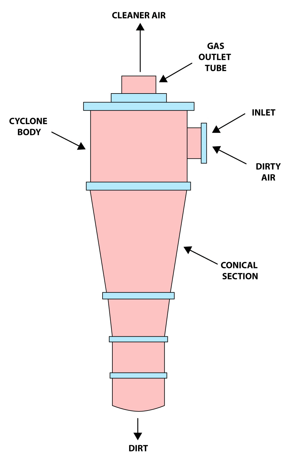
Cyclone Separator With Labels
How Cyclone Separators Work
The below video is an extract from our
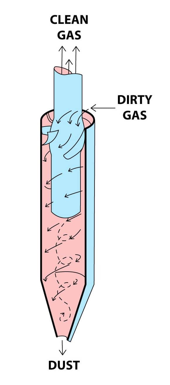
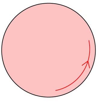
Gas containing entrained particles enters at high velocity through the tangential inlet at the top of the cyclone. The gas flows into the cyclone body/barrel at a tangent and begins to flow in a circular downward spiral towards the lower reject port; this downward flowing spiral is referred to as a spiral vortex.

Tangent Line (shown in red)
The cone diameter gradually decreases which causes the gas velocity to increase. The outer vortex creates an additional inner vortex closer to the centre of the separator body and this inner vortex flows spirally upwards towards the accept port.

Inner (blue) and Outer (black) Vortex
Particles with more inertia will impact with the side of the cyclone whilst particles with lower inertia will remain within the gas stream. Inertia can be thought of as a particle’s ability to continue travelling in a straight line even when external forces are applied. When an external force is applied -such as by the cyclonic vortex- the particles with low inertia will not continue to travel in a straight line, they will instead travel spirally as they are swept along by the gas stream.
Entrained Low Inertia Gas Particles
Particles with greater inertia will be less affected by the vortex and will continue travelling in a straight line. This straight-line trajectory causes the high inertia particles to move out of the gas stream and impact with the cyclone separator body. These particles then fall to the base of the cyclone separator and out of the reject port. In this way, entrained particles of a certain size can be separated from the gas stream.

Entrained High Inertia Gas Particles
Another way to think of this process, is to think of higher density particles colliding with the cyclone body whilst less denser particles are retained within the gas stream. This is not strictly true though as both the density and shape of the particle will affect its ability to be separated from the gas stream.
Particles discharged through the reject port are usually either recycled (off or on site), or, disposed of.
Physics Note
It is a common misconception that centrifugal force is the force that separates the particles from the gas stream, but it is centripetal force that causes the particles to collide with the separator body.
The below equation is used to calculate the centripetal force based on the air velocity (v), particle size (m) and radial distance (r) from the cyclone wall.
F =(mv2)/r
Where: v = air velocity
m = particle size
r = radial distance
Centripetal forces generated within the separator may be anywhere between five times gravity for large diameter low pressure drop separators, to 2,500 times gravity for very small diameter high pressure drop separators.
Factors Effecting Efficiency
There are several factors that can affect a cyclone separators efficiency. These include particle density, particle size, volumetric flow rate, pressure drop, cone length, body length, ratio of accept port to body diameter, and even the smoothness of the cyclone’s internal surfaces. We will now discuss the more important design aspects in greater detail.
Particle density is one of the most deciding factors affecting a cyclone’s ability to remove entrained particles. Dense particulates such as ferrous oxides can be separated with a 99% or greater efficiency, irrespective of particle size. When the particle density decreases, the efficiency decreases (assuming no other system changes occur).
Particle size is a large design consideration effecting a separator’s efficiency. Larger particles can be more easily separated than smaller particles. Particles smaller than five microns are difficult to separate without using very small separators. Particle exceeding 200 microns can often be separated using other means such as gravity-settling chambers. A reduction in particle size will give a corresponding reduction in efficiency.
A separator’s geometry greatly impacts the efficiency of the unit. A larger diameter cyclone separator will not be able to separate particles as efficiently as a smaller diameter separator. The efficiency of the separator increases as the cone diameter decreases. Thus, reducing the cone diameter enables the removal of finer and finer particles. A small diameter cone will extract much finer particles from a gas stream than a larger diameter cone.
All cyclone separators have an associated pressure drop. The pressure drop can be thought of as the amount of energy required to move the gas through the separator, alternatively, it can be thought of as the amount of resistance the cyclone separator adds to the system flow. The pressure drop is a product of the gas flow rate, gas density and cyclone geometry. Pressure drop can be expressed as:
DR = Ra Inlet - Ra Outlet
Where:
DR = Cyclone Pressure Drop
Ra = Absolute Pressure
Another way to increase a separator‘s efficiency is to reduce the accept port diameter. This changes the separator body to accept port diameter ratio and has the effect of only allowing finer particles to leave the separator through the accept port.
Large or Small Separator?
Small cyclone separators have a higher efficiency rating, but the associated pressure drop is high and the volumetric flow rate is low. Gas velocity through small separators is also very high and this will lead to a high level of erosion if the gas stream contains abrasive particles.
Large cyclone separators have a lower efficiency rating, but the associated pressure drop is low and the volumetric flow rate high. A large diameter separator is not suitable for removing fine particles from a gas stream.
Advantages and Disadvantages
There are many advantages associated with cyclone separators, some of these include:
- Cheap to purchase.
- Low maintenance.
- Suitable for high temperatures.
- Suitable for liquid mists.
- Do not require much space.
Some disadvantages are associated with cyclone separators, but these disadvantages can be reduced in severity if the correct separator is selected for the correct application. Disadvantages may include:
- Increased operating costs associated with the pressure drop (assuming large pressure drop).
- Inefficient when handling small/fine particles.
- Not suitable for ‘sticky’ substances.
Material Selection
Material selection is a very important consideration when choosing a separator for a specific application. Some process systems may contain erosive or corrosive flowing mediums, so it is necessary to add a protection layer to the cyclone’s internal surfaces.
Suitable materials for protecting the separator within erosive systems might include materials such as ceramic or some form of enamel. Separators operating within corrosive systems may have some form of enamel or poly-based material coating to protect the cyclone metal body beneath.
Applications
Cyclone separators are utilised in many applications due to their low cost, simple design and high efficiency. Cyclone separators require no bags or filters and require only low maintenance.
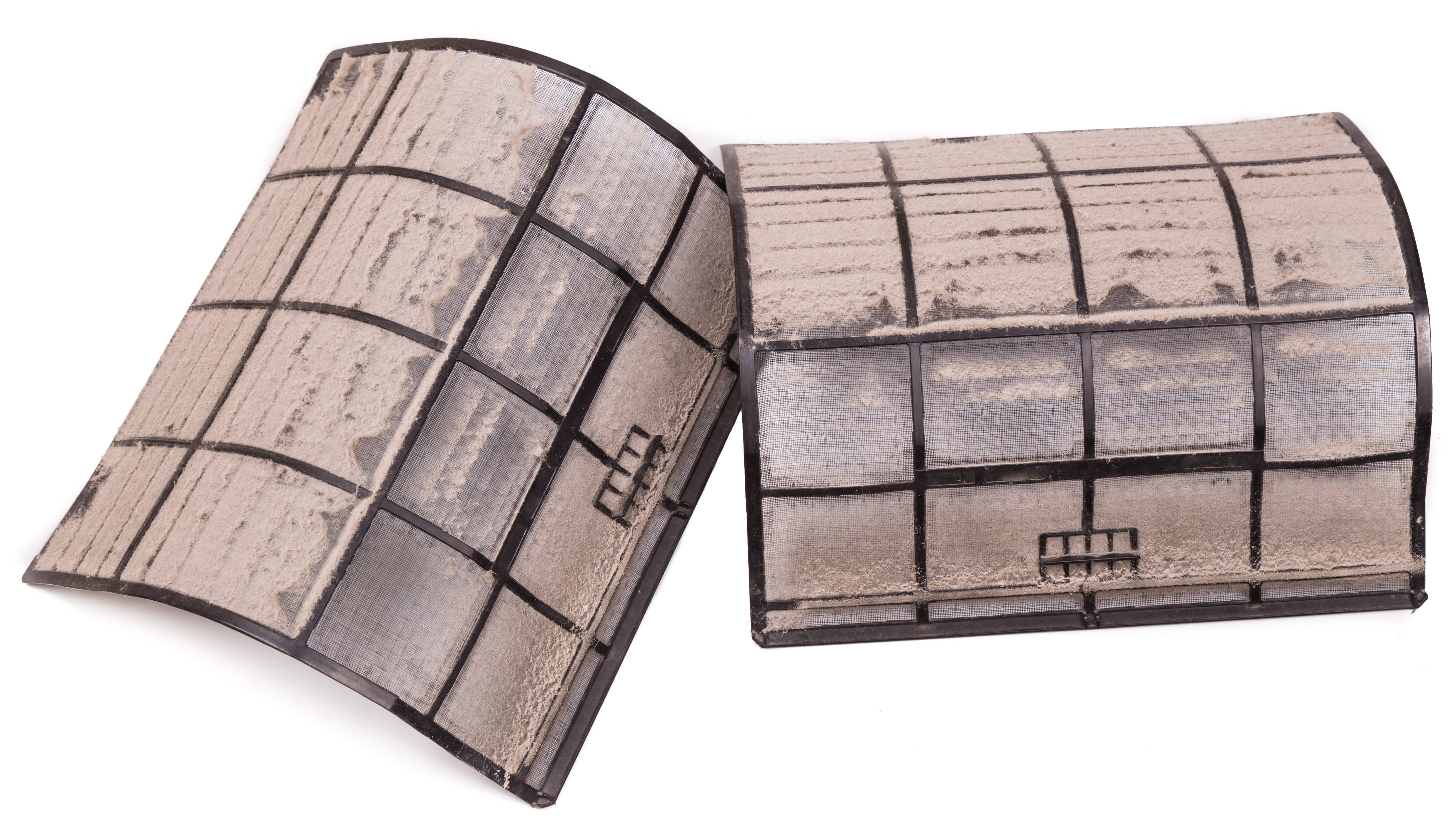
Dirty Filters
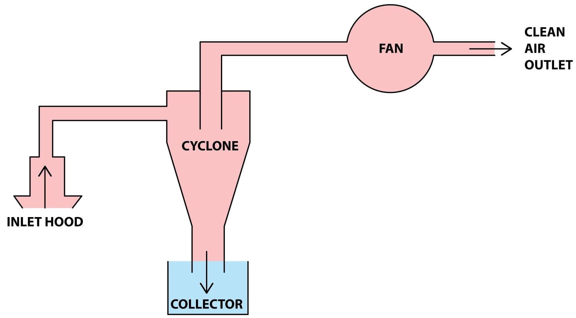
A typical application would include a saw mill. Saw mills generate a lot of dust which must be extracted from the mill. Dust is drawn into the main extraction system by a negative pressure created by a fan -usually a centrifugal fan-. The dust laden air then passes through a cyclone separator where most of the wood dust is separated from the air stream; the clean air is then discharged directly to ambient air whilst the wood dust is recycled or disposed of.
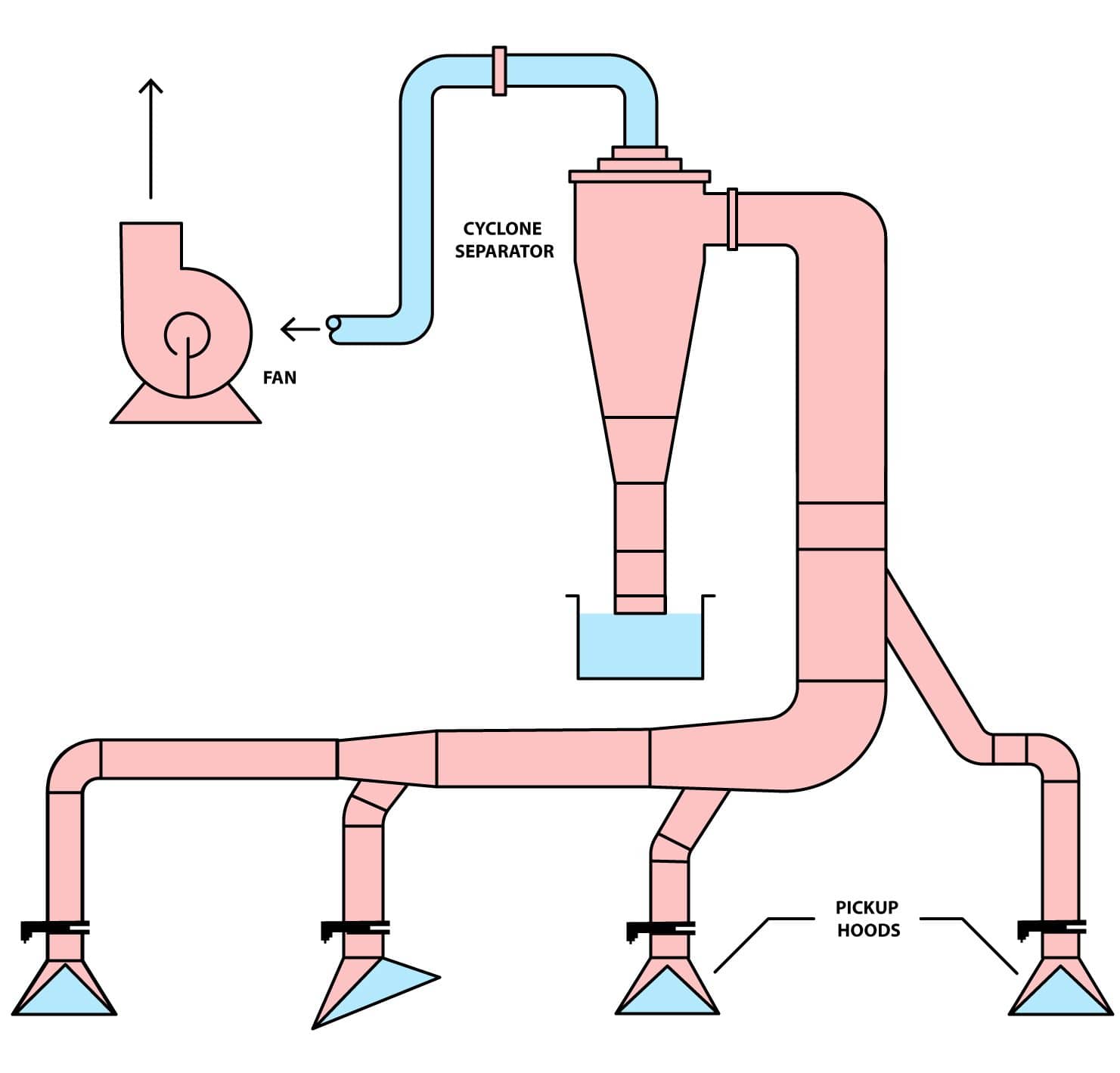
Cyclone Separator Wood Mill Setup
Another common application is the household vacuum cleaner. An electric motor drives a fan which draws air and particles into the vacuum cleaner body. There are few parts to maintain and the vacuum has the added advantage of having no bags that need to be replaced. James Dyson made himself a billionaire when he invented the first cyclone separator vacuum cleaner after seeing a working cyclone in a wood mill.
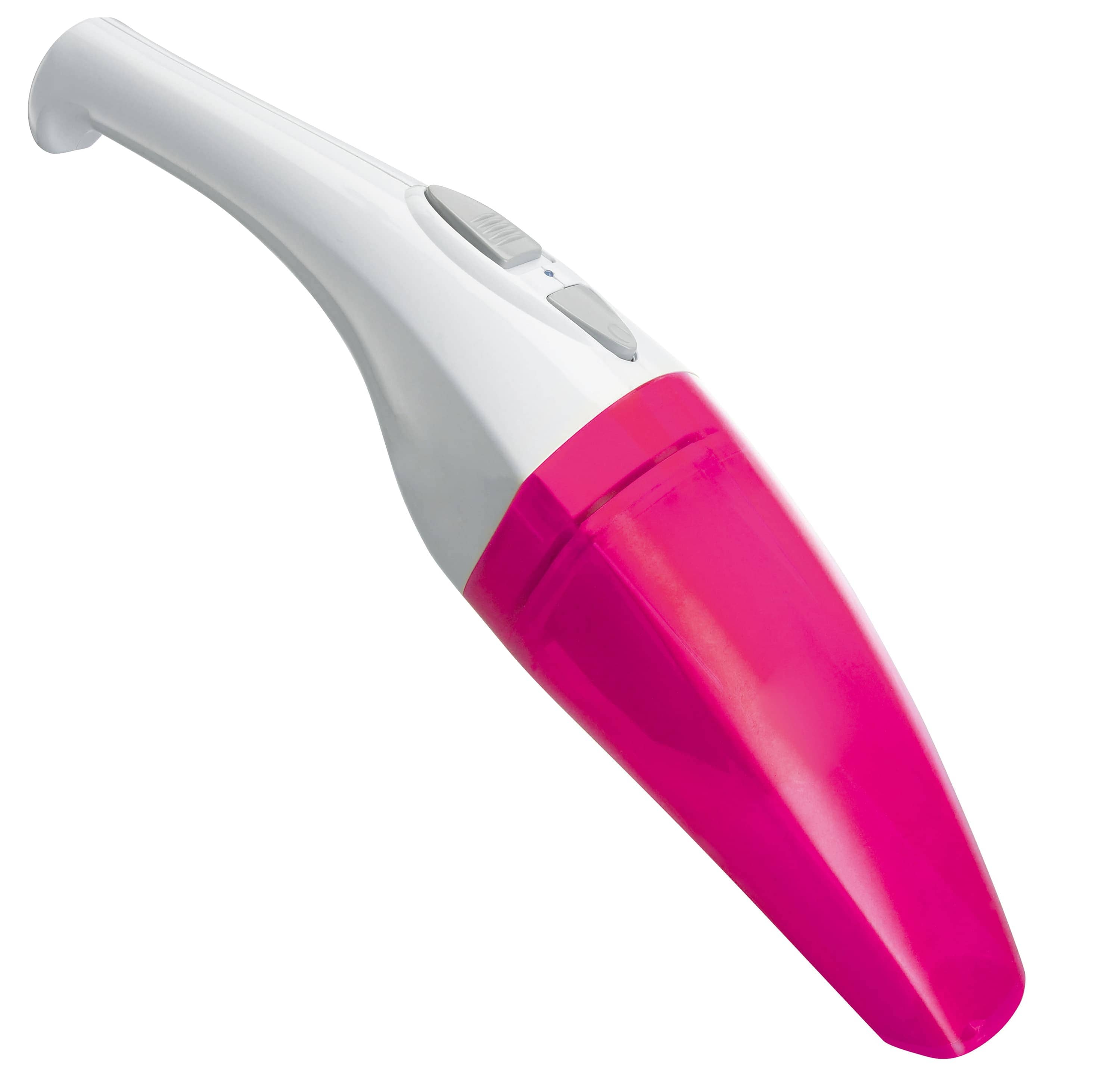
Cyclone Separator Vacuum Cleaner
Additional Resources
https://energyeducation.ca/encyclopedia/Cyclone_separator
https://en.wikipedia.org/wiki/Cyclonic_separation
https://www.sciencedirect.com/topics/engineering/cyclone-separator