


Quick Introduction
Four stroke internal combustion (IC) engines have been used for over 100 years and their design has not changed significantly since this time. Each of a four stroke engine's strokes is used for one stage of the combustion cycle i.e. there is one stroke for each of the suction, compression, power, and exhaust stages. It’s called a four-stroke combustion engine because there are four strokes to one combustion cycle. One stroke is defined as the maximum distance a piston moves when traveling from the top of the cylinder, to the bottom of the cylinder, or vice versa. For example, when the piston moves from the bottom of the cylinder to the top, this is called a stroke. Likewise, if the piston moves from the top of the cylinder to the bottom, this is also called a stroke.
Compared to two stroke engines, four stroke engines have more components and weigh more, but are more efficient. Four stroke engines may be fired on many different fuels, including gasoline/petrol, diesel, gas (methane) and bio-oils (to name a few fuel types).
Four Stroke Engine Animation
Four Stroke Engine Components
Four stroke engine designs vary, so the number and type of components used per design also varies. For example, common rail engines employ different engine parts compared to non-common rail engines.
Enjoying this article? Then be sure to check out our Internal Combustion Engines Video Course! The course has a quiz, handbook, and you will receive a certificate when you finish the course. Enjoy!
Components
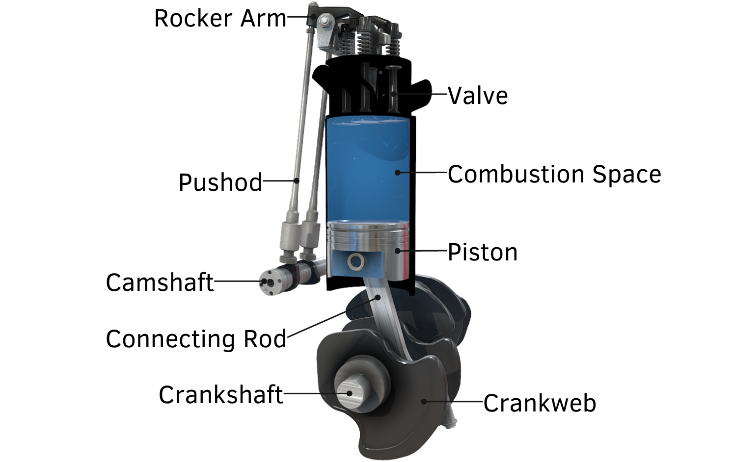
Common four stroke engine components include:
- Piston
- Connecting Rod (Con Rod)
- Plain Bearings
- Crankshaft
- Camshaft
- Combustion Space (Cylinder Liner)
- Inlet Valves and Exhaust Valves
- Pushrods
- Rocker Arms
- Fuel Injectors
Access the below 3D model if you would like to learn all of an engine's main components and some engine terminology.
Engine Components and Terminology
Note: The type of engine shown in this 3D model utilises direct fuel injection with common rail fuel injectors.
The below video is an extract from our Internal Combustion Engine Basics Online Video Course.
How Four Stroke Engines Work
A four stroke engine requires four strokes to complete one combustion cycle. The strokes are:
- Suction (Intake)
- Compression
- Power (Ignition)
- Exhaust
Another way to remember the strokes and their order is to change the wording to:
Stroke 1 = Suction (suck)
Stroke 2 = Compression (squeeze)
Stroke 3 = Power (bang!)
Stroke 4 = Exhaust (blow)
Below is a brief summary concerning what occurs at each stage of the combustion cycle:
Suction Stroke: Also known as the induction or intake stroke. The piston moves downwards, drawing air into the cylinder, via air inlet valves.
Compression stroke: The air inlet valves close, and the piston moves upwards compressing the air within the cylinder. Fuel is injected shortly before the piston reaches the top of cylinder.
Ignition stroke: Also known as the power or combustion stoke. The fuel is ignited causing a controlled explosion. Combustion of the fuel causes an increase in pressure and temperature within the cylinder, which results in the piston being pushed away from the top of the cylinder.
Exhaust stroke: Exhaust gasses are discharged from the cylinder as the piston moves upwards, from the bottom to the top of the cylinder.
How Four Stroke Engines Work - Detailed
A more detailed look at what occurs at each stage of the combustion cycle is given below.
Suction Stroke
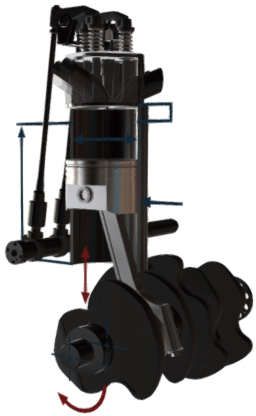
The suction stroke draws air into the cylinder liner (combustion space) as the piston moves down towards bottom dead centre (BDC). When the piston reaches BDC, the inlet valves close and the piston travels back upwards towards top dead centre (TDC); this is the compression stroke.

Four Stroke Engine With TDC and BDC Indicated
Compression Stroke
As the piston moves towards TDC, the air in the cylinder is compressed (volume reduces) and its temperature and pressure increases. Shortly before TDC, fuel is injected into the combustion space. The fuel ignites and a controlled explosion occurs.
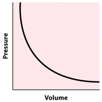
Pressure and Volume Graph
Power Stroke
Once ignition occurs, the power stroke begins. The increase in pressure and temperature created by combustion pushes the piston towards BDC. Once at BDC, all the fuel within the combustion space has been burnt and the final engine stroke is ready to begin. Another term for the 'power stroke' is the 'ignition stroke'.
Exhaust Stroke
The exhaust stroke is the fourth and final stroke. The piston moves from BDC to TDC and expels exhaust gas from the combustion space via the exhaust gas valves. Once the piston reaches TDC, the air inlet valves open and the exhaust valves close a short time later (there is some valve overlap to ensure all exhaust gas has been removed from the combustion space). The combustion cycle is now complete as all four strokes have occurred.
Spark Ignition and Compression Ignition Engines
Petrol/gasoline engines use spark plugs for ignition, whilst diesel engines use only the heat generated due to compression. For this reason, petrol engines are known as spark ignition engines and diesel engines are known as compression ignition engines.
3D Model Details
This 3D model shows each stage of the four stroke engine cycle. Blue indicates suction and compression whilst red indicates expansion (power) and exhaust. The valves and other components are all correctly timed to show the entire four stroke process.
Related Online Engineering Courses
Internal Combustion Engine Basics
Diesel Engine Fundamentals (Part 1)
Diesel Engine Fundamentals (Part 2)
Crankcase Explosion Relief Valves Explained
How Centrifugal Governor Works
Anti-Friction Bearing Fundamentals
Additional Resources
http://www.animatedengines.com/otto.html
https://en.wikipedia.org/wiki/Four-stroke_engine
https://www.merchantnavydecoded.com/four-stroke-engine/