

Alternating Current Generator: Introduction
Synchronous Alternating current (AC) generators are the predominant type of generator used for electrical power generation in the power engineering industry. Over 95% of all electrical power consumed today is produced from three phase (3~) alternating current electric generators. The working principle of all AC generators relies upon Faraday’s law of electromagnetic induction.

Diesel Engine Connected to an AC Generator
Faraday’s Law
Two physical laws determine how almost all of the electrical engineering industry works.
- Faraday’s Law – a changing magnetic field will induce a voltage in any conductor within that field.
- Ampere’s Law – electrical current flowing in a conductor creates a magnetic field around that conductor.

Ampere’s Law - Magnetic Fields Created Around Conductors Due to Current Flow
Enjoying this article? Then be sure to check out our Engineering Video Courses! Each course has a quiz, handbook, and you will receive a certificate when you finish the course. Enjoy!
Conventional and True Current Flow (Hole Flow)
When current (measured in Amps) flows through a conductor, a magnetic field is created around that conductor. The direction of the magnetic field depends upon the direction of current flow.
Right-Hand Rule
The right-hand rule shows the direction of the magnetic field based on conventional current flow (positive to negative). The right-hand rule is termed so because if a hand grips a conductor, the thumb will indicate the direction of current flow whilst the fingers wrapped-around the conductor will indicate the direction of the magnetic field.

Right-Hand Rule
Left-Hand Rule
The left-hand rule shows the direction of the magnetic field based on true current flow (negative to positive). Most electrical engineering industries use conventional current flow whilst electronic industries favour true current flow (also known as ‘hole flow’). For most applications, the direction of current flow is not important, so the historical error made when assuming current flows from positive to negative, was never corrected.
Important – Most publications use the RIGHT-HAND RULE. Assume conventional current flow unless otherwise stated.

Left-Hand Rule
Fleming’s Left-Hand Rule
It is useful to be aware of another left-hand rule which is used far more than the left-hand rule previously mentioned; this left hand-rule is called ‘Fleming’s left-hand rule’.
Fleming’s left-hand rule is used to determine the force imparted on a live (electrically charged) conductor when placed within a magnetic field. Fleming’s left-hand rule is often used to determine the direction of rotation for electric motors.

Fleming’s Left-Hand Rule
Faraday’s Law
Faraday’s law will now be discussed in further detail because it is directly related to how electricity is generated (Ampere’s law will be discussed later).
Faraday’s law states that if a conductor moves through a magnetic field, a voltage (electric potential difference) will be induced in that conductor. Likewise, a voltage will be induced in a stationary conductor if it is located within a changing magnetic field. No voltage will be induced if the magnetic field is static (not changing).

Magnet with Magnetic Field Lines
Note that Faraday’s law is also referred to as ‘Faraday’s law of electromagnetic induction’. The terms ‘magnetic induction’ and ‘electromagnetic induction’ have the same meaning and are used interchangeably.
Magnetic Fields
Magnetic fields are represented by drawing a series of lines extending from one end of a magnet to the other.
- Stronger magnetic fields are represented by closely packed magnetic field lines.
- Weaker magnetic fields are spaced further from each other.
A magnet’s field strength is proportional to the distance from the magnet i.e. the field strength is stronger closest to the magnet and becomes weaker as the distance from the magnet increases.
Conductors
A conductor is any substance that allows current flow (allows electrons to flow). Some conductors have better conductivity (ability to conduct current) properties than others. In electrical engineering, copper and aluminium are popular conductors because they have high conductivity.

Copper Wiring (Copper Conductor Strands)
How AC Generators Work
Faraday’s law states that a voltage is induced in any conductor that is placed within a changing magnetic field; this process of induction is known as ‘electromagnetic induction’. In order to generate alternating current (AC) voltage, we must therefore either:
- Constantly move a conductor through a stationary magnetic field.
- Constantly move a magnetic field across a stationary conductor.
Large scale power generation facilities produce electricity using the ‘constantly move a magnetic field across a stationary conductor’ option. Power stations are not simple constructions, but the fundamental principles of how electricity is generated by over 95% of power stations, are shown below.
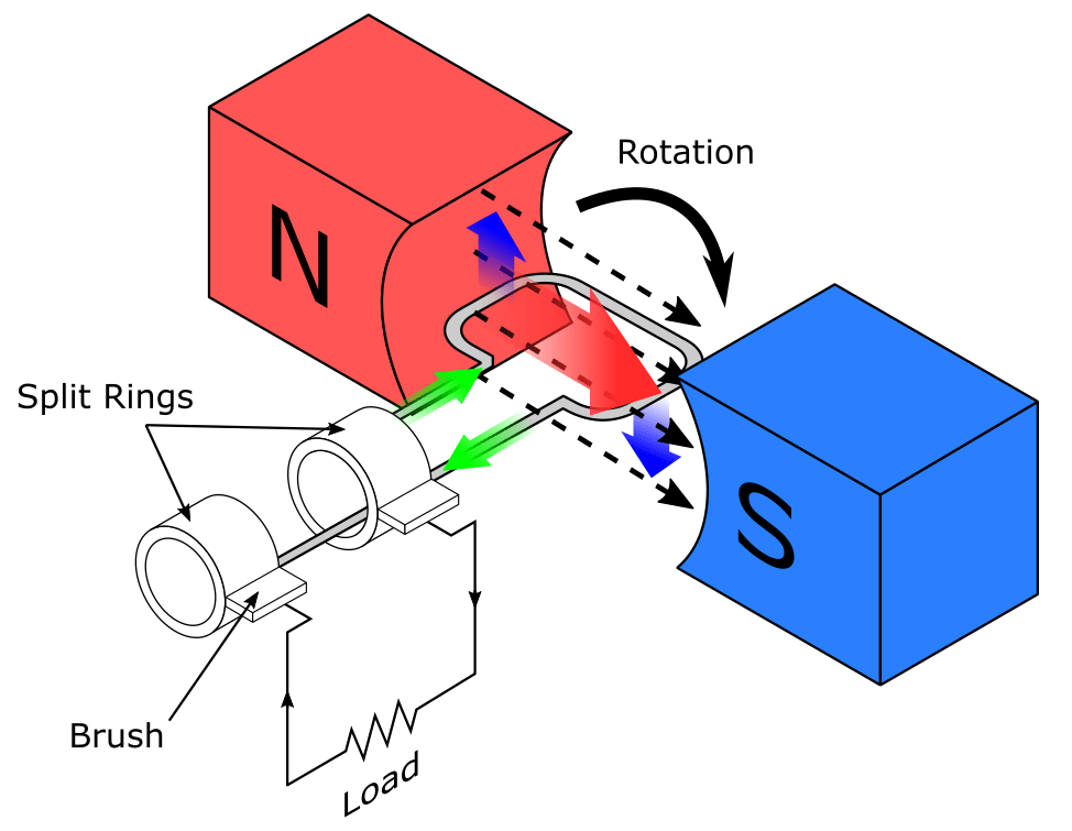
Conductor Moving Through A Stationary Magnetic Field
Note that the above image shows a rotating conductor, but power stations have stationary conductors and rotating magnets (reverse of setup shown on the image).
To generate power, a magnet is needed and a means of moving that magnet continuously so that the magnetic field constantly changes. Its possible to move the magnet back and forth linearly (in a straight line), but this would be slightly impractical and inefficient. The most economical way to keep magnetic field lines constantly moving, is by rotating/spinning the magnet. This can be achieved easily by attaching the magnet to a machine whose output is rotary motion. For example, by attaching an output shaft to the below machines, and then coupling a magnet to the output shaft, we can transfer the machine’s rotary motion (mechanical power) to the magnet:
- Diesel engine.
- Steam turbine.
- Combustion turbine.
- Hydroelectric turbine (Kaplan, Francis, Pelton).
- Wind turbine.
In the real world, the above machines are referred to as ‘prime movers’ because they transfer the mechanical power needed by a generator to produce electrical power. It is important to realise that ‘generators’ do not ‘generate’ electrical energy. It is only possible to transfer energy from one form to another.
Energy cannot be destroyed or created/generated (First Law of Thermodynamics)
Prime movers transfer mechanical energy to generators via a shaft and/or gearbox. Generators convert mechanical energy to electrical energy.
Basic Power Generation Example
The below video is an extract from our Mechanical and Electrical Engineering Explained Online Video Course.
To simulate a prime mover, we can physically attach a magnet to the output shaft of a water wheel (hydro turbine). Water passes over the water wheel which causes it to rotate and consequently the magnet rotates. If the water supply is continuous, the water wheel rotates continuously, as does the magnet. Now that a means of continuously changing the magnetic field have been found, a conductor must be placed within the changing magnetic field so that a voltage can be induced.

Basic AC Power Generation Setup
Placing a single conductor within the magnetic field would not induce much voltage within that conductor, but if the conductor is wrapped into the shape of a coil, it’s possible to induce much more voltage. To make voltage induction even more efficient, the conductor can be installed as close to the magnet as possible. In addition, adding more loops to the coil will induce more voltage, whilst removing loops from the coil will induce less voltage.
When the magnet is spinning and a conductor has been placed within the magnetic field, voltage will be induced in the conductor. If the conductor is connected to a closed electrical circuit, alternating current will flow. Electricity can now be delivered/dispatched to consumers for use!

Basic AC Power Generation Example
Generator Rotor
Industrial generators rely upon more complicated components than simple magnets and coils, but the working principles of power generation remains the same. The rotating magnet of a generator is referred to as a ‘rotor’ whilst the coil is referred to as a ‘stator’. It is possible for the stator to act as the magnet and the rotor to act as the coil, but this setup will not be discussed at this time.
A rotor normally consists of a series of magnets mounted onto a laminated core of thin steel plates; the thin steel laminated plates are referred to as ‘laminations’. Laminations influence the shape of the magnetic field because steel contains iron, which is magnetic (capable of acting as a magnet or being attracted by a magnet). In addition, laminations focus the magnetic field so that as many magnetic lines as possible intersect with the conductor. Focussing the magnetic field improves a generator’s efficiency because the voltage induced in a conductor increases, as the number of magnetic field lines intersecting the conductor increases.
For real world applications, the basic ‘magnet rotating near a coil’ example described earlier would not allow us to meet our civilisation’s electrical power demands. Permanent magnets are not practical to work with (difficult to transport, pose safety hazards etc.) and are expensive. An alternative form of magnet is required, this requirement is met by electromagnets.
Tip: A permanent magnet is one whose North and South poles are fixed and do not change. Permanent magnets are also known as ‘ferromagnets’.

Permanent Magnets
What is Ampere’s law?
Before discussing electromagnets, its necessary to understand Ampere’s law.
Ampere’s Law states that electrical current flowing in a conductor creates a magnetic field around that conductor. The strength of the magnetic field created is proportional to the amount of current flow. Direct current flows in one direction and the resultant magnetic field size and polarity is constant. Alternating current flows in two directions and the results are:
- The magnetic field size increases and decreases.
- The magnetic field strength increases and decreases.
- The polarity of the magnetic field reverses (North to South then South to North).
The above results occur in sync with the changing direction of the electrical current. A sine wave is used to indicate the strength of the magnetic field over time and its polarity (North is positive, South is negative).

Sine Wave Changing Over Time
What is polarity?
Permanent Magnets have a North and South pole. If the South and North poles of the magnet reverse their positions (so that North becomes South and South becomes North), the polarity is said to be ‘reversed’.
Electromagnets
As previously mentioned, Ampere’s law states that ‘electrical current flowing in a conductor creates a magnetic field around that conductor’.
If direct current (DC) is flowing in a conductor, the magnetic field will be constant.
If alternating current (AC) is flowing in a conductor, the magnetic field will vary (expand and contract).
The strength of a magnetic field surrounding a conductor is proportional to the amount of current flowing through the conductor.
It’s possible to create a focused magnetic field by wrapping a conductor into the shape of a coil. If current flows through the coil, a North and South pole at each end of the coil will effectively be created.

Magnetic Field Due to Current Flowing Through a Coil
An electromagnet is created when current flows through a coil and a resultant North and South magnetic pole form. Note that the position of North and South can be reversed by reversing the direction of current flow. Direct current would create a fixed North and South pole because current flow is in one direction only. Alternating current would create varying North and South poles because current flows is in two directions (back and forth).
If coils are installed on a generator rotor, it’s possible to apply an electrical current to these coils in order to create an electromagnet. Installing multiple coils on the rotor allows for multiple North and South magnetic poles to be created. Creating a generator’s magnetic field using electromagnets has several significant advantages compared to using permanent magnets:
- Controlling the current fed to the electromagnet(s) makes it possible to control the strength of the magnetic field, thus its possible to control how much voltage is induced in the stator windings (conductor coils).
- Varying the number of coils used by an electromagnet determines the potential magnetic field strength that an electromagnet can create; this is an important and useful characteristic during the design process.
- Coil materials are generally much easier to obtain, maintain, and/or replace, than large permanent magnets.
- Electromagnets are cheaper compared to large permanent magnets.
- Electromagnets are easier to handle than large permanent magnets.
What are ‘generator rotor poles’?
Generator rotors are sometimes referred to as having ‘2-poles’, or, ‘4-poles’ etc. The ‘poles’ refer to the North or South pole of a magnet. A 2-pole rotor has one South and one North pole. A 4-pole rotor has two North and two South poles etc.
Electric Generator Stator
The conductor coils surrounding a rotor are collectively called a ‘stator’. Surrounding the rotor with a coil, or series of coils, ensures that the magnetic field lines produced by the rotor intersect with a large area of the coil(s), this yields more induced voltage.
A stator with a single coil would induce single phase (1~) voltage. Installing more coils produces additional phases. A ‘phase’ is the voltage potential measured across a single conductor. Inducing voltage in 3 separate coils at the exact same time would not be practical because the electrical system would cycle heavily between positive and negative voltage, and it would not be possible to install the coils in exactly the same physical space. Installing three coils 120 degrees apart allows voltage to be induced in three separate coils in a more balanced manner. Power stations produce 3 phase ac voltage.

Three Phase AC Voltage
Electrical Power (P=VI)
Electrical power is represented by the equation:
P = V I
Power = Voltage x Current
It can be deduced from the above equation that power will always be 0 if the value of voltage is 0, or if the value of current is 0. An open circuit has no current flow, but if the circuit is closed, current will flow (if current is present). Whilst it is possible to have voltage without current, it is not possible to have current without voltage. To produce electrical power, we must therefore have both voltage and a closed circuit for current flow.
How Power Stations Generate Electricity
Irrespective of which type of power station (power plant) is being considered, over 95% of them use the fundamental principle of ‘constantly move a magnetic field across a stationary conductor’ to generate electrical power. For example:
- Coal fired power station (and any fossil fuel fired power station) – burns fuel to release its chemical energy as heat, which is then used to turn water to steam. The steam is fed to a steam turbine, which causes the turbine to rotate. The resultant mechanical power from the turbine is transferred to a generator via a shaft (and usually gearbox).
- Wind turbine – wind passes over a wind turbine’s rotor blades, which causes the blades to rotate. The rotary motion (kinetic energy) from the blades is fed to a generator.
- Nuclear power station – generates heat (thermal energy) to raise the temperature of water; the water is then fed to a heat exchanger. Water on the shell side of the shell and tube heat exchanger turns to steam as it is heated; this steam is then fed to a steam turbine which is connected to a generator.
- Hydroelectric power station (dam, pumped storage, tidal stream, tidal barrage, run-of-the-river) – water is fed to a turbine runner, which causes the runner to rotate. The runner is connected on a shaft to a generator.

Hydroelectric Turbine Runner and Generator
- Solar furnace – electromagnetic waves from the sun are focused onto a specific point (solar furnace) in order to generate a large amount of heat at that point. A thermal fluid (often molten salt) absorbs the heat and transfers it to water via a heat exchanger. The water changes phase to steam and the steam is fed to a steam turbine, which is connected to a generator.
Related Online Engineering Courses
Synchronous Electrical Generators
How To Make Electricity (Power Generation)
Additional Resources
https://en.wikipedia.org/wiki/Electricity_generation
https://www.eia.gov/energyexplained/electricity/how-electricity-is-generated.php