


Introduction
Electrical bushings are essential components for a wide range of electrical equipment such as power transformers, shunt reactors, circuit breakers, and capacitors. These seemingly simple devices perform the critical function of carrying current at high voltage through equipment enclosures. They perform this function by providing an insulating barrier between the live conductor and the metallic (conducting) body of the electrical apparatus (which is at ground potential).
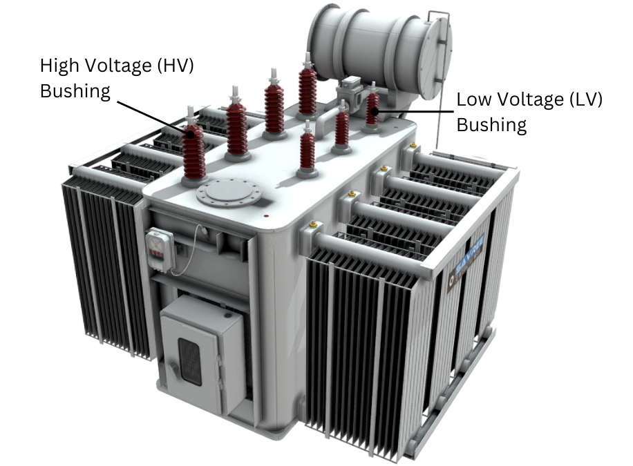
Power Transformer Bushings Highlighted
Classification and Construction
Electrical bushings can be broadly divided into two major categories depending upon how they are built and assembled:
- Bulk or Non-condenser Type
- Condenser Type
Enjoying this article? Then be sure to check out our Introduction to Electrical Bushings Video Course! The course has a quiz, handbook, and you will receive a certificate when you finish the course. Enjoy!
How Electrical Bushings Work
The below video is an extract from our Electrical Bushings Course Online Video Course.
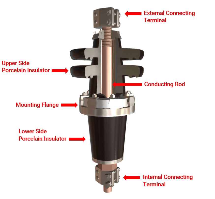
Bulk Type Bushings
A bulk type bushing consists of a central conducting rod usually manufactured from copper or aluminium, which is encased by an insulator. The surrounding insulator may be manufactured from porcelain or composite resin silicon rubber.
Whilst the traditional porcelain insulator offers mechanical sturdiness and a long service life, the application of silicon rubber is becoming increasingly popular due to its lower cost, ease of handling, and its surface hydrophobicity (which reduces the risk of pollution related flashovers). Due to dielectric strength limitations, the use of bulk type bushings is restricted to system voltages of 72 kV and below.
Condenser Bushings
At higher system voltages, condenser bushings are used. Compared to bulk type bushings, condenser bushings are relatively complex in their construction. In order to cope with the high electric field stresses generated at high voltage, condenser bushings are formed from an inner capacitance-graded insulated core, which is sandwiched between the central current carrying tube and external insulator.
The condenser core consists of coaxial layers of electrical grade Kraft paper and conducting foil inserts of varying lengths. Foil inserts are located at fixed radial intervals, which aids in distributing and stabilising the electric field across the bushing insulation. These conducting inserts mimic the capacitive elements (connected in series) that link the high voltage conductor of the bushing to ground. For this reason, condenser bushings are sometimes referred to as capacitance-graded bushings.
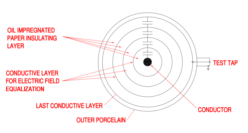
Cross-Section of Condenser Bushing
To further increase a bushing’s dielectric strength, the condenser insulation is saturated with mineral oil, or curable epoxy resin; these two technologies are referred to as oil impregnated paper (OIP) and resin impregnated paper (RIP), respectively.
The material of the external insulator is invariably porcelain for OIP condensers and silicon rubber for RIP condensers, both serving the same purpose of limiting the flow of leakage current and preventing external flashovers. OIP condenser bushings are also fitted with a spring-loaded expansion chamber to allow for oil volume fluctuations (expansion/contraction) due to varying temperature (a conservator tank on a power transformer performs a similar purpose).
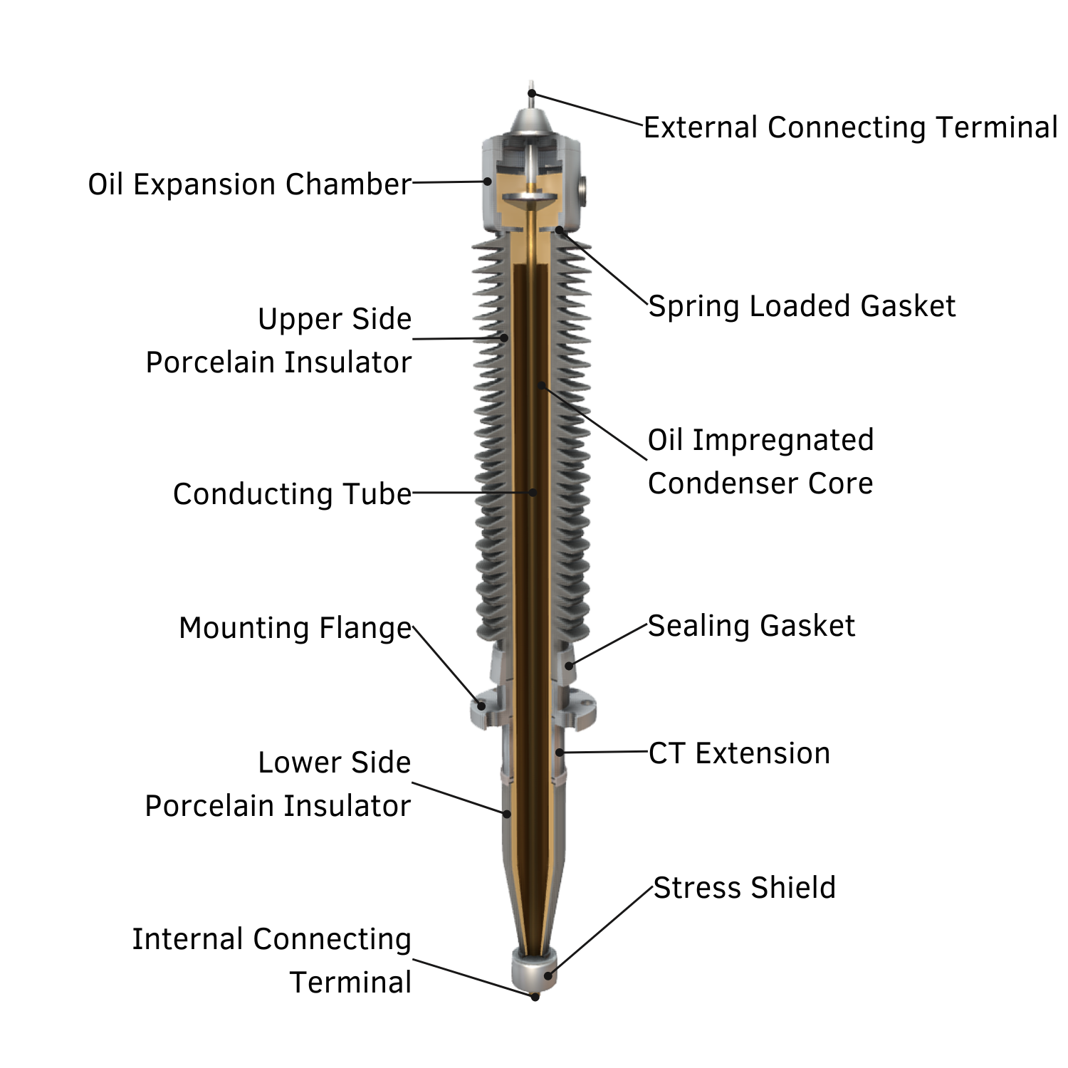
Oil Impregnated Condenser Bushing
Condenser bushing mounting flanges are equipped with a test tap (more on this below) and additional space for the installation of a ring type current transformer (CT). Internal connecting terminals are fitted with stress shields to limit high potential stresses inside the oil-filled enclosure.
Condition Assessment
The test tap is connected to the outermost condenser foil and is used to perform two important benchmark measurements. These measurements are capacitance (C) and dissipation factor (tanδ); both tests are used to determine a bushing’s insulation condition.
Any increase in C and/or tanδ values indicates insulation deterioration, moisture ingress, and/or short circuiting of condenser foils. Insulation resistance tests, partial discharge measurements, and thermographic inspections, are also useful aids when assessing a bushing’s condition.
Applications
In the power engineering industry, the most common applications for bushings are:
- Air-to-Oil – used in outdoor air insulated substation (AIS) equipment, such as transformers and shunt reactors etc.
- Air-to-Gas – used in gas insulated substations (GIS) and SF6 circuit breakers.
- Air-to-Air – used for outdoor to indoor connections e.g. wall bushings.

Installation of a Transformer Air-to-Oil Condenser Bushing
Design Requirements
The design of any type of electrical bushing takes into account the following requirements and aspects:
- The central conductor of a bushing should be able to carry the anticipated load, or fault currents, without overheating the surrounding insulation (which can lead to abnormal loss of life).
- For any given transformer, the conducting rod of a low voltage (LV) bushing is required to carry a higher current than its high voltage (HV) counterpart. Consequently, the conducting rod of a LV bushing is always thicker (has a larger diameter) than its HV counterpart.
- A bushing’s internal insulation must be able to withstand the nominal operating and occasional transient electric field stresses placed upon it. These stresses arise due to the potential differences between the live conductor and grounded external surroundings. A bushing’s internal insulation should also limit the inception of partial discharges (PD), which can cause progressive deterioration of the insulation.
- A bushing’s external insulation should provide sufficient dry arcing distance to withstand lightning strikes and switch impulses. The external insulation should also provide adequate creepage distance (leakage distance) to prevent excessive flow of leakage current; leakage current can result from a combination of pollution accumulation (dirt, sand, salt etc.) and/or ambient moisture.
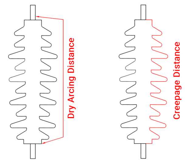
Bushing Dry Arcing and Creepage Distance
- A bushing’s cantilever strength should be high enough to cope with the anticipated mechanical stresses that will be placed upon the bushing during seismic and short circuit events.
- A bushing’s design and construction should be robust enough to withstand the rigours of transportation, handling and installation.
Related Online Engineering Courses
Introduction to Electrical Transformers
How Electrical Transformers Work
Electrical Transformer Health Assessment
Why Are Transformers Rated in VA not W?
Electrical Substations Explained
Additional Resources
https://en.wikipedia.org/wiki/Bushing_(electrical)
https://electrical-engineering-portal.com/purpose-and-maintenance-of-transformer-bushings