


Introduction
Counter flow induced draft cooling towers are a common cooling tower design employed in the engineering world. Other common designs include the cross flow induced draft cooling tower and counter flow natural draft cooling tower.
How Counter Flow Cooling Towers Work
The below video is an extract from our Introduction to Cooling Towers Online Video Course.
Cool cooling water is pumped from the cooling tower basin to the process. The cool cooling water is heated by the process and its temperature increases. The warm cooling water is then pumped back to the cooling tower to be cooled.
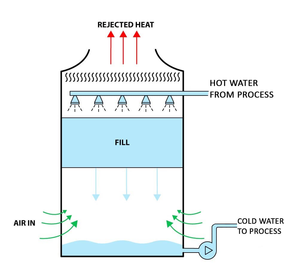
Counter Flow Cooling Tower Process Diagram
Incoming warm water enters the distribution manifold and is discharged through spray nozzles inside the tower. Spray nozzles spray the warm water evenly over the entire fill. The water passes downwards through the fill (heat exchanger) whilst air passes upwards. As the water travels through the fill, some of it evaporates which causes the remaining water to be cooled (evaporative cooling).
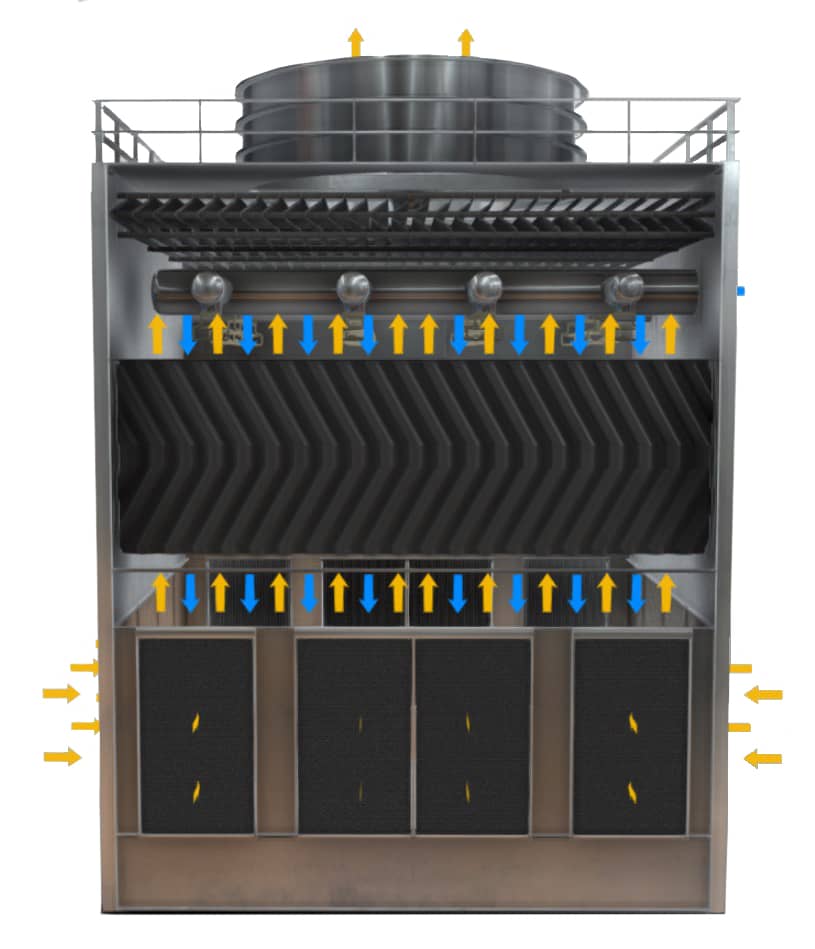
Counter Flow Cooling Tower Cross Section (water blue, air yellow)
The cooled water that did not evaporate falls into the collection basin due to gravity, whilst the air continues its path upwards, through the drift eliminator, through the axial fan, then exits through the top of the tower.
Short Recap
- Water enters the tower and travels downwards.
- Air is induced into the base of the tower by a fan and travels upwards.
- Some of the water evaporates as it passes through the fill and this cools the remaining water (evaporative cooling) that falls into the basin.
- A portion of the evaporated water is reclaimed by the drift eliminator, whilst the rest is discharged through the top of the tower as drift (water loss).
This is the process description for a wet counter flow induced draft cooling tower, there are other wet cooling tower designs commonly used, but the working principle (evaporative cooling) is the same.
3D Model Components
This 3D model shows all major components associated with a typical induced draft counter flow cooling tower, these include:
- Fill (Heat Exchanger)
- Spray Nozzles
- Piping
- Basin
- Drift Eliminator
- Casing/Shell
- Fan
Related Online Engineering Courses
Introduction to Cooling Towers
Introduction to Industrial Chiller Plants
Plate Heat Exchanger Fundamentals
Additional Resources
https://en.wikipedia.org/wiki/Cooling_tower
https://www.hamon.com/solutions/wet-cooling-towers/induced-draft/