


Introduction
Transformers are used for increasing or decreasing voltage (referred to as ‘step-up’ and ‘step-down’ transformers respectively). Transformers can be roughly split into two groups:
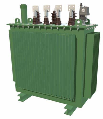
- Liquid Immersed - the transformer core and windings are placed within a tank and immersed within insulating liquid (usually mineral oil).
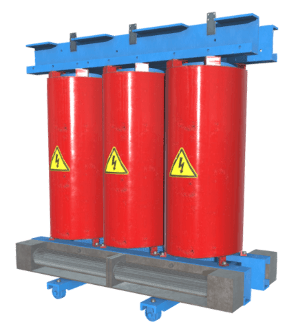
- Dry - the transformer has no tank and is air cooled.
There are many different types of electrical transformer in service today, but three designs are very common; these are:
- Conservator - the transformer tank is connected to an expansion tank. Conservator types are used for high kVA ratings.
- Hermetic - the transformer tank is hermetically sealed (no connection to atmosphere). Hermetic transformers are generally used for lower kVA applications.
- Dry - used for low-medium kVA applications. Dry transformers are also used when immersed transformers represent too great a fire risk (the mineral oil in immersed transformers increases the fire load).
How Liquid Insulated Transformer Work
The below video is an extract from our Introduction to Electrical Transformers Online Video Course.
Transformer Parts and Functions
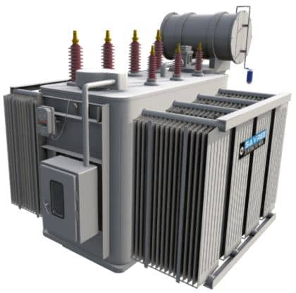
3D Model Details
This 3D model shows all major components associated with a typical liquid insulated electrical transformer, these include:
- Silica Gel Cartridge
- Breather
- Gas Actuated Relay
- On Load Tap Changer (OLTC)
- Windings
- Thermometer
- Bushings
- Magnetic Oil Gauge (MOG)
- Core
- Tank
- OLTC Control Box
3D Model Annotations
Low Voltage Bushing
The external low voltage electrical circuit is connected to the transformer windings via a central conductor in the bushings. Low voltage bushings are shorter in length than high voltage bushings whilst also having larger centre conductors (higher current carrying capacity requires a thicker conductor).
High Voltage Bushing
The high voltage electrical circuit is connected to the high voltage transformer windings via bushings. Bushings are used to pass electrical conductors through partitions/barriers without raising the electrical potential of the partition/barrier. Bushing conductors are usually manufactured from copper or aluminium. The exterior of the bushing is usually manufactured from porcelain or silicone.
Temperature Gauge
A local temperature gauge indicates the transformer’s insulating liquid temperature. A local sensor is used to relay the transformer insulating liquid temperature to a remote location. Local gauges should be large enough to allow easy reading by personnel, ideally without entering the transformer enclosure (assuming the transformer is not installed in a vault).
Gas Actuated Relay
A gas actuated relay protects the transformer should small or large electrical faults occur within the transformer tank. A Buchholz relay has the additional safety feature of shutting-down the transformer should a low insulating liquid level occur.
Heat Exchanger / Radiator
As a transformer is electrically loaded, it generates more heat. Smaller transformers are air cooled whilst larger units are liquid cooled. Fans and pumps can be used to increase the cooling capacity of the transformer radiator still further. Transformers with pumps and fans are force cooled, whilst those without pumps and fans are naturally cooled.
Tank
The transformer tank contains the windings, laminate core and insulating liquid. The tank is usually constructed of steel and externally coated with corrosion resistant paint. Smaller transformers are usually hermetically sealed, but larger units are ‘free breathing’ (expel and inhale air through the conservator tank).
Magnetic Oil Gauge (MOG)
A magnetic oil gauge (MOG) indicates the oil level within the conservator tank. The gauge is linked to a float inside the tank via a magnetic coupling, thus no penetrations through the conservator tank are required.
Tap Changer
Smaller transformers employ no tap changer, or, an off-load tap changer (LTC). Larger units utilise on-load tap changers (OLTC). The tap changer regulates the secondary voltage by a given percentage, each tap correlates to a certain % of the total output voltage.
Breather
A breather is used to allow for the expansion and contraction of insulating liquid due to the varying temperature of the transformer. The breather prevents moisture and particle ingress into the conservator tank; this reduces the likelihood of the insulating liquid becoming contaminated. Silica gel is the most common drying agent although alternatives are available.
Core
The transformer core consists of thin laminated steel plates. Each plate is pressed and held together using steel straps, or adhesive. The shape of the core is designed to focus the magnetic field in order to maximise the transformer’s efficiency. Plates are used (rather than a solid block of metal) to reduce hysteresis and eddy current losses.
Windings
A transformer requires high and low voltage windings to operate; these windings are also referred to as primary and secondary windings. The low voltage windings are wound around each limb of the core, and the high voltage windings are wrapped around the low voltage windings.
Related Online Engineering Courses
Introduction to Electrical Transformers
How Electrical Transformers Work
Electrical Transformer Health Assessment
Electrical Substations Explained
Why Are Transformers Rated in VA not W?
Additional Resources
https://en.wikipedia.org/wiki/Transformer_oil
https://electrical-engineering-portal.com/transformer-constructions
https://www.usbr.gov/tsc/techreferences/mands/mands-pdfs/Trnsfrmr.pdf