


Introduction
A Pelton turbine is a type of hydroelectric turbine employed in the power generation industry. Unlike the Francis turbine and Kaplan turbine, Pelton turbines are impulse type turbines.
Although Pelton turbines are very efficient, they are not as common as Kaplan and Francis turbines because the Pelton turbine requires a very large head of pressure (difference in elevation between the upper and lower reservoir) to operate; this restricts its use to certain geographical areas only.

Hydroelectric power plants belong to the renewable energy sector and are classified as a 'green' form of power generation.
History
The Pelton turbine was invented by Lester Allan Pelton in the 1870s. Lester Pelton was not the first to try to use impulse energy to drive a water turbine, but he was the first to make an efficient impulse water turbine.

Lester Pelton's Original Design
Impulse Turbines
Impulse turbines convert kinetic energy to mechanical energy. The part of the turbine that converts kinetic energy to mechanical energy is known as the runner. The part of the turbine that converts mechanical energy to electrical energy is known as the generator.

The Pelton runner consists of a series of curved buckets mounted onto the outer periphery of a round shaped wheel. For this reason, a Pelton runner is sometimes referred to as a Pelton wheel.

Enjoying this article? Then be sure to check out our Hydroelectric Power Plants Video Course! The course has a quiz, handbook, and you will receive a certificate when you finish the course. Enjoy!
Pelton Turbine Components
Buckets
The buckets, or impulse blades, are cast into two cup shapes adjacent to each other. These buckets ‘catch’ the water jet and direct the flow gradually backwards. Due to the bucket design, almost all of the kinetic energy from the water is harnessed as torque prior to discharge.
Wheel
The Pelton wheel is very heavy and acts as a flywheel. A flywheel stores rotational energy and resists changes to rotational speed. The amount of energy stored in the flywheel is the square root of its rotational speed.
Drive Shaft
The drive shaft connects the turbine runner to the generator, this makes it possible to convert the mechanical energy from the rotating runner into electrical energy. Pelton turbines can be used as prime movers for other rotating assets also e.g. a mechanical pump.
Spear/Needle
The spear/needle controls the flow of water through the nozzle and thus the amount of force exerted upon the wheel. Not all Pelton wheels have a spear or needle.
Spear Adjuster
The spear adjuster can be operated manually, electrically or hydraulically. Large Pelton turbines actuate the spear adjuster hydraulically only.
How Pelton Turbines Work
Water is delivered through a pressurised water conductor known as a penstock. The penstock forms the suction side of the turbine and connects the upper reservoir to the turbine. At the end of the Penstock is a spray nozzle.
The spray nozzle converts the potential energy of the water to kinetic energy, this kinetic energy manifests itself as a high velocity jet of water that is sprayed out of the nozzle and towards the Pelton runner buckets. The water jet impacts with the inside surface of each bucket tangentially.

Power Plant Using Pelton Turbines
Each bucket consists of two halves separated by a high ridge, known as a splitter. The splitter divides the water jet so that the flow to both sides of the bucket is even. A notch on each bucket allows the water jet to flow into each bucket at an optimum angle. The spoon shape of the bucket causes the kinetic energy of the water jet to be converted to mechanical energy gradually, as the water completes a 180-degree turn in the bucket. The mechanical energy manifests itself as torque on the runner shaft, which causes the runner to rotate. After leaving the bucket, the water is discharged through a discharge pit.
Because the Pelton runner is connected on a common shaft to a generator, the generator begins to generate electricity as soon as the runner rotates. The generator converts the mechanical energy supplied by the runner to electrical energy, which can then be transferred through an electrical grid to end consumers.
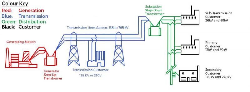
Electrical Grid
Flow Control
A needle (or spear) regulates the nozzle water jet. The needle can be retracted to allow full flow, or pressed against the nozzle to stop flow entirely. In the event of emergency, water can be sprayed at the back of the runner buckets to bring it to a standstill.
Impulse Explained
Force applied over a period of time is known as impulse. Impulse is applied to the runner buckets for the entire time the water jet impacts upon the bucket. Impulse causes the Pelton runner to rotate by changing its momentum. Due to the nature of impulse, a large force applied for a short period of time, will cause the same change in momentum as a small force applied over a long period of time. As impulse is used to change the momentum of Pelton turbines, Pelton turbines are classified as impulse turbines and the buckets are also referred to as impulse blades.

Pelton Turbine Buckets
Interesting Characteristics
Pelton turbines are suitable for high head, low flow applications. Typically, they are installed in areas where sudden drops in elevation are a natural feature of the local terrain.

Hydro Turbine Flow and Head Ranges
The Pelton runner rotates in air, under atmospheric conditions, Pelton turbines are thus pressure-less turbines.
Most Pelton turbines use between one to five nozzles.
It is possible to mount one, or multiple, Pelton runners onto a single shaft.
The efficiency of Pelton turbines often exceeds 90% when the right operating conditions are met.
Unlike reaction water turbines, Pelton turbines require no draft tube because they operate in a pressure-less environment.
Pelton turbines can be horizontally or vertically orientated. Smaller units tend to be horizontally orientated, whilst larger units tend to be vertically orientated.
Pelton turbines can be big. The largest Pelton runners in the world have a diameter of 4.6 metres and operate with a head of over 1,800 metres. Each runner is fed from a Penstock that is charged to 200 bar pressure. Five spray nozzles per runner create jets of water that leave each nozzle at 192 metres/second. Each runner is rated at more than 400 MW.
3D Model Components
This 3D model shows all major components associated with a typical Pelton hydroelectric turbine, these include:
- Suction Inlet
- Discharge
- Pelton Runner (Buckets and Wheel)
- Bearings
- Casing
- Drive Shaft
- Speed Adjuster Handle
- Needle/Spear
Related Online Engineering Courses
Introduction to Hydroelectric Power Plants
Hydroelectric Power Plants Overview
Additional Resources
https://energyeducation.ca/encyclopedia/Pelton_turbine
https://themechanicalengineering.com/pelton-wheel-turbine
https://en.wikipedia.org/wiki/Pelton_wheel