


What are steam turbines?
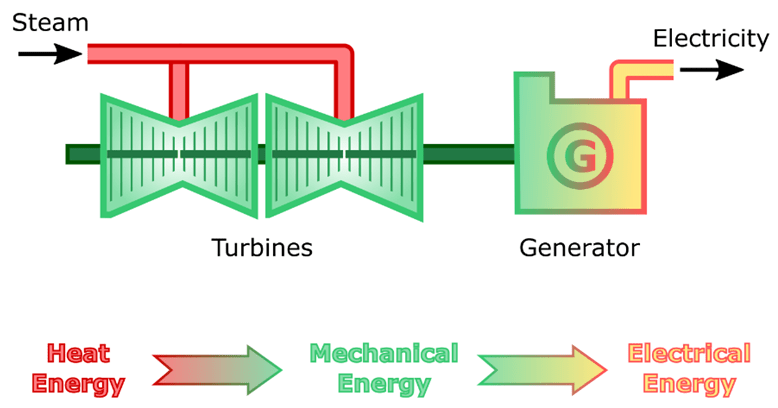
Steam turbines are a common site at many industrial plants. The applications of steam turbines are numerous due to their high efficiency and high reliability. Although steam turbines can be used as prime movers to drive pumps and other small/medium sized machinery items, they are most commonly associated with the power generation industry, where they are used to provide mechanical power to a generator, thus producing electricity. Another common application of steam turbine’s is for ship propulsion.
Typical Power Generation Steam Turbine Installation
This article discusses the history of steam turbines, their main components, designs, how they work, their associated system (oil, steam etc.) and factors affecting their efficiency.
History of Steam Turbines
Steam turbines have been mentioned in history as far back as the 1st century, but the modern steam turbine design was created in 1884 and is accredited to the engineer Charles Parsons. Mr Parsonsbecame one of the founders of the power generation industry after he constructed an electrical generating set using a direct coupled steam turbine as the prime mover. This initial simple design was patented and later became a great commercial success.
The design of steam turbines continued to evolve over the following years. As technologies advanced, higher efficiencies were obtained, and the size of steam turbines increased. Steam turbines are now powering some of the world’s largest electrical generators. Over 80% of all electricity generated today is generated using steam turbine prime movers.
There were previously many turbine manufactures such as Pametrada, British Thompson Houston, Parsons, John Brown, Kawasaki, Westinghouse, Curtis, Stal Laval etc. but the current market is dominated by relatively few manufacturers, such as Siemens, General Electric, Alstom, Toshiba and Mitsubishi Heavy Industries.
Enjoying this article? Then be sure to check out our Engineering Video Courses. Each course has a quiz, handbook, and you will receive a certificate when you finish the course. Enjoy!
Steam Turbine Applications
Steam turbines are used as prime movers where the conversion of heat energy into mechanical rotary motion is required. Applications of steam turbines include large power stations, ship propulsion, compressors, and even small pumps.
What are impulse and reaction turbines?
Steam turbines can be classified as either reaction, impulse, or a mixture of both; a large steam turbine will almost always have both impulse and reaction stages.
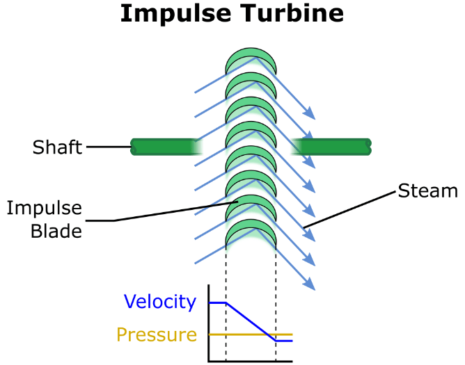
Impulse Turbine
An impulse turbine uses steam impinging upon the turbine rotor blades to rotate the turbine rotor. As the velocity of the steam is directly proportional to the amount of energy transferred to the rotor, the velocity of the steam is increased using nozzles prior to it impinging upon the rotor blades.
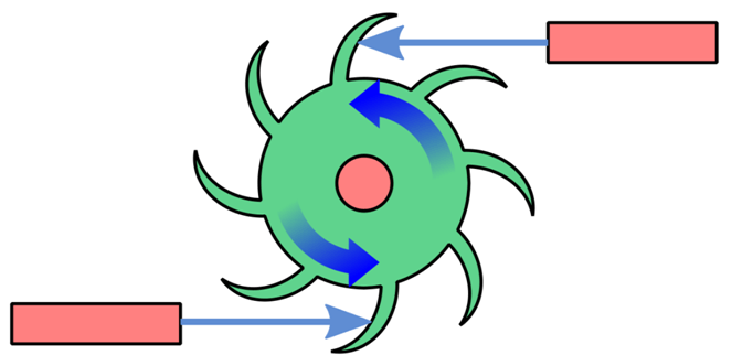
Impulse Turbine Design
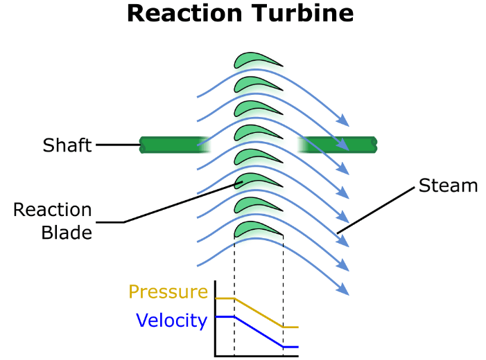
Reaction Turbine
A reaction turbine uses the reactionary force of the steam changing direction over the blades to rotate the rotor. As steam passes over a reaction turbine blade, a reactionary force is created upon the blade and this causes the turbine rotor to rotate.
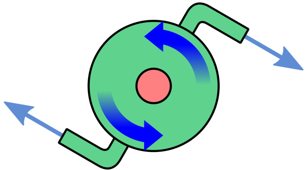
Reaction Turbine Design
Despite reaction turbines being classified as ‘reaction’, there is always a small degree of force imparted due to impulse. For this reason, they are also called impulse reaction blades.
Impulse and Reaction Blades
What are back-pressure and condensing steam turbines?
Steam turbines can be classified as either back-pressure or condensing.
Back-Pressure Steam Turbines
A back-pressure steam turbine reduces the pressure of the inlet steam to the steam turbine’s design back pressure. The exhaust steam from the turbine can then be used for process requirements e.g. heating tanks, comfort heating etc. Back pressure steam turbines are commonly used in industrial plants that require a large amount of process steam e.g. oil seed extraction plants and crude oil refineries. Note that back-pressure steam turbines are a type of non-condensing turbine.
Condensing Steam Turbines
Condensing steam turbines are used if the turbine is utilised solely for power generation i.e. it is connected to a generator and does not provide process steam to the plant. Unfortunately, the exhaust steam of condenser steam turbines must be condensed prior to being returned to the boiler (this is where condenser turbines obtain their name). This intentional cooling of the steam inherently leads to an efficiency reduction, due to the rejection of heat from the steam system.
Back-pressure turbines do not require a condenser as they exhaust steam at higher pressures; this steam is then used as process steam. Exhaust steam in a back-pressure turbine is not reduced to vacuum pressure, whereas a condenser turbine is. The total difference between the inlet and exhaust steam pressure of a turbine is what ultimately determines its overall efficiency. Therefore, a condenser steam turbine is more efficient than a back-pressure (non-condensing) steam turbine despite rejecting heat through a condenser. For power generation purposes, a typical condensing turbine may achieve operating efficiencies between 30-40%, compared to a non-condensing turbine which may achieve 15-35%. However, non-condensing turbines are cheaper.
Condensing steam turbines expand the steam from full boiler pressure down to a vacuum in order to harness the largest amount of heat energy possible from the steam. As we have already established, condensers have a negative effect on the system from an efficiency perspective, because we are rejecting heat. If the amount of waste steam discharged to the condenser can be reduced, this will result in efficiency gains. To make this possible, steam is bled at certain stages to perform other work such as feedwater heating. Whenever steam is bled, it is referred to as bleed steam, or extraction steam. Examples of bleed steam applications include condensate and boiler feed water heating (the steam is passed through a shell and tube heat exchanger). Bleed/extraction steam systems increase overall turbine efficiency because more heat from the steam is recovered rather than rejected.
In summary, both condenser and non-condensing turbine designs have advantages and disadvantages which have to be accounted for at the design stage in order to ensure the correct turbine design is suitable for its application. Selecting the correct turbine type is essential to obtaining a high overall plant efficiency.
What are the main parts of a steam turbine?
The diagram below shows basic steam turbine components.
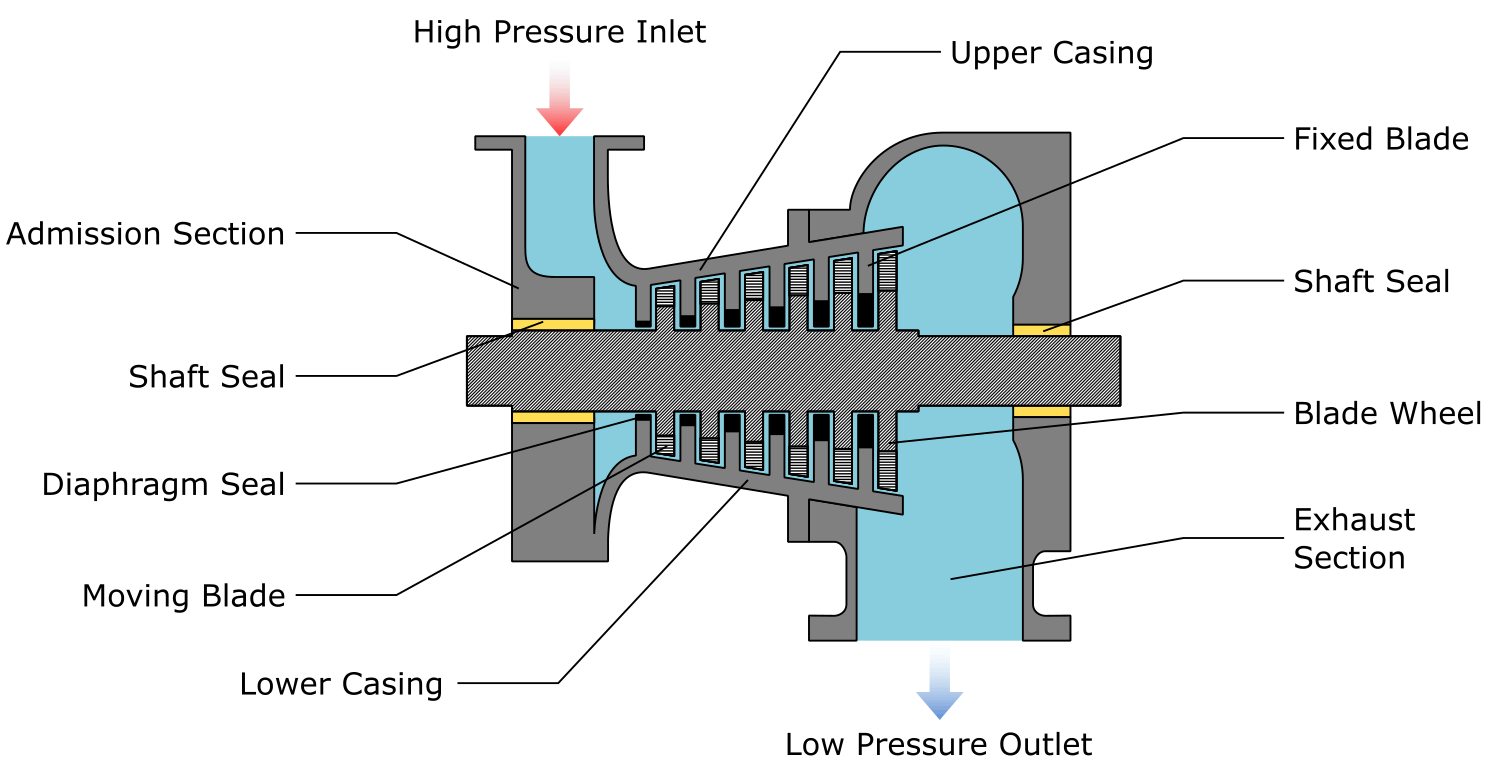
Steam Turbine Construction and Parts
Casing/Cylinder
Steam turbine casings/cylinders are cylindrical shaped constructions consisting of two halves. Due to their shape, they are referred to as ‘cylinders’ as well as ‘casings’. The casing forms the largest pressure boundary of the steam turbine. Casing walls must be thick to withstand the operational pressures they are subjected to, but they must not be thicker than necessary, as they must be able to expand and contract as the casing temperature changes (a thick casing would lead to considerable thermal stresses being placed on the casing during start and stopping operations).
Turbine casings are split along the horizontal axis to form an upper and lower casing; the two casings are bolted together to form a split casing. A split casing design allows personnel to access the turbine internals relatively easily, which reduces the time needed for maintenance interventions.
Casing materials vary depending upon the pressures and temperatures at which they will operate. Casings are classified as High Pressure (HP), Intermediate Pressure (IP) and Low Pressure (LP).
HP and IP casings are made from cast chrome molybdenum steel in order to withstand the effects of high temperature and creep (physical deformation due to heat applied over prolonged periods of time). HP and IP casings have a considerable weight and thickness to withstand the steam system pressures at which they operate.
LP turbines operate at lower pressures and temperatures than IP and HP turbines. Consequently, the casing material of an LP turbine can have lower mechanical strength; LP casings are often constructed from carbon steel. Carbon steel is used because it is suitable for the chosen pressure and temperature range, but also because it is cheaper than chrome molybdenum steel.
Rotor Shaft
The rotor forms the central shaft of the turbine; it is installed along a horizontal axis through the centre of the turbine casing. Rotor discs are mounted directly onto the rotor shaft, and rotor blades are mounted to the rotor discs. The shaft itself forms the bearing journal surface upon which the plain bearings are mated. The load of the turbine (generator, pump etc.) is connected either directly to the rotor shaft, or, indirectly via a gearbox.
Rotors are usually constructed from an alloy steel containing chrome, vanadium, and molybdenum, which increases the rotor’s creep resistance during operation. A rotor’s actual construction material depends upon the operational stresses it will encounter. For example, low pressure turbines may use common alloys that are not as expensive as those used for IP and HP turbines. Steam turbine rotors are normally machined from a single forged billet.
Rotor Discs
Moving rotor blades are attached to rotor discs which are mounted on the rotor shaft.
Moving Blades
There are two types of blade within a steam turbine, these are classified as moving blades, and stationary blades. Moving blades are responsible for transferring the heat energy from the steam to the rotor. Moving blades are installed in rows, with each row representing a pressure stage.
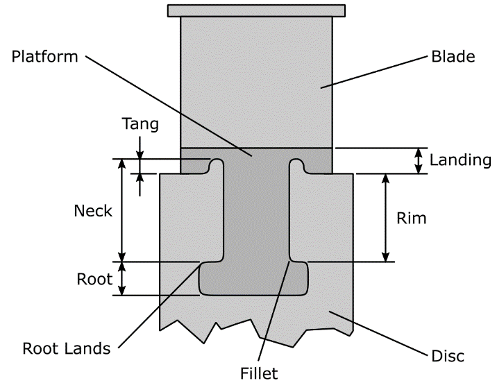
Moving Rotor Blade and Rotor Disc
Moving blades are attached to rotor discs via the blade root; one of the most common blade root designs is the fir tree design, although alternatives exist (T-root, multi-finger etc.). The blade root e.g. fir tree, retains the blade in its correct position on its associated rotor disc.
Moving blades are forged and then machined from single billets. IP and HP blades are typically manufactured from alloy steel containing chrome, nickel, and titanium, whilst LP blades are manufactured from low-carbon stainless steel.
Blades must be mechanically strong as they transmit all the power harnessed from the steam, to the rotor. Each blade must also be able to cope with the operational stresses placed upon it, these stresses include high temperature variations, high pressure variations, mechanical stresses from vibration, erosive effects of foreign object damage (water or rust particles etc.), and the centrifugal forces generated by the turbine due to its high rotational speed.
Rotor
The rotor shaft and everything mounted to it (moving blades, rotor discs etc.), forms the rotor. The term rotor is often not clearly defined, which leads to some confusion concerning which components belong to the rotor. Another name for the rotor is the ‘rotor assembly’.
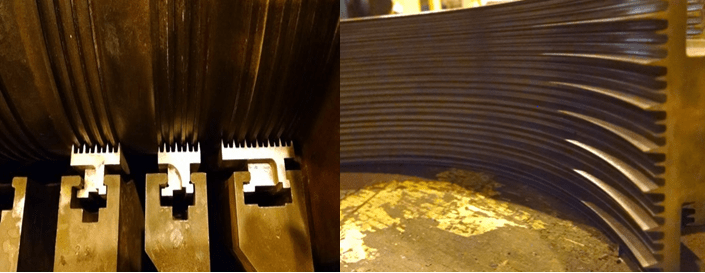
Diaphragms
Steam turbine diaphragms are hollow disc shaped objects that house a turbine’s stationary blades (fixed blades). Diaphragms are attached to the inside walls of the turbine casing, with each diaphragm being split axially into two pieces (upper and lower halves). Housing diaphragms within the casing reduces the likelihood of axial movement of the diaphragms.
Each diaphragm disc holds a single row of stationary blades and each blade row is referred to as a ‘stage’ (same terminology as with a turbine’s rotor). In addition to housing the stationary blades, diaphragms form a pressure boundary that separates each of the pressure stages.
Diaphragms are constructed from carbon steel, or in some cases cast iron, which is machined and then welded into place. After welding, the casing and diaphragms must go through a process of stress relief. Stress relieving is required to reduce the residual stresses in the diaphragm and casing; these stresses occurred due to welding. If the process of stress relieving does not take place, physical distortion may occur as the temperature of the turbine varies e.g. during a turbine’s heating-up and cooling-down.
Nozzle Boxes
Nozzle boxes increase the velocity of steam prior to its entry to the first stage of a HP turbine. Due to the steam’s velocity increase, a corresponding pressure decrease also occurs. A single nozzle box contains multiple nozzles. Nozzles are subject to very high temperatures and severe erosion conditions. For this reason, they are cast from a hard stellite material which is an alloy of cobalt, chrome, tungsten, and molybdenum.
Labyrinth Glands
Labyrinth gland seals are used to seal the space between the rotor shaft and casing; they are designed to stop steam leakage out of the casing, and air leakage into the casing. Air leakage can cause cracking of hot blades and will reduce the likelihood that a constant vacuum within the steam turbine condenser can be maintained.
Fins and segments on the rotor shaft and casing create a torturous flow path for steam and air. Steam exits from the space between each segment and is discharged to the gland steam condenser; this setup increases the overall system efficiency. During low power operation, gland steam continues to be supplied to the gland seal in order to stop air entry. Most gland seals operate at a pressure of approximately 0.25 bar (3.6 psi) and have make-up and spill valves to maintain the correct pressure irrespective of the turbine’s load condition.
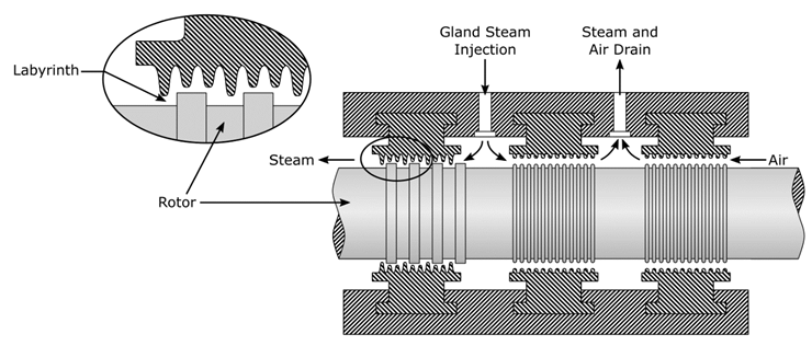
Steam Turbine Labyrinth Seal Schematic
Labyrinth Sealing Arrangement
Casing Supports/ Panting Beams
To allow for the effects of varying temperature conditions i.e. thermal expansion and contraction, the turbine casing, and all components, must be able to expand and contract. The standard setup is to have the drive end of the turbine fixed and stationary whilst the opposite end is free to move axially. Although some contraction and expansion occurs radially, most occurs along the axial axis. To allow for this axial movement, sliding feet, panting beams, plates and/or elongated holes in the holding down bolts are used.
Coupling
To cater for any misalignment and axial movement, turbines are sometimes connected to a gearbox or generator via a flexible coupling; this is normally a gear coupling which is filled with grease or lubricated from the gearbox oil tank.
Condenser
Condensers, also sometimes called ‘surface condensers’, are large heat exchangers used to cool exhaust steam back into condensate; they are usually installed directly beneath the turbine but may be installed axially in some instances. Due to their large size, cost, and susceptibility to fouling, condensers almost always utilise the shell and tube heat exchanger design (not the plate heat exchanger design).
Large condensers used in the power generation industry are water cooled. Water enters water boxes mounted at opposite ends of the condenser. After flowing out of the inlet water box, water flows through tubes to the discharge/outlet water boxes on the opposite side of the condenser.
Condensers rely upon high water flow rates to ensure the temperature rise (ΔT) across the tubes is minimal; a low temperature rise helps maintain a condenser’s vacuum and correspondingly a turbine’s high operating efficiency. Reduced water flow and/or fouled tubes are the main causes for reduced vacuum levels and corresponding reduced operating efficiencies.
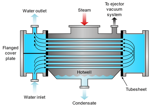
Surface Condenser Diagram
A condenser’s vacuum is normally created by steam driven air ejectors or by electrically driven liquid ring vacuum pumps.

Steam Ejector
Condensers can significantly impact the efficiency of a steam turbine. If exhaust steam - and the resulting condensate - is cooled far below its saturation temperature, energy is being unnecessarily lost. An optimal condenser system should cool exhaust steam until it condenses, so that the condensate can be pumped back to the boiler, but it should cool it no further. Exhaust steam should not be excessively cooled because this will lead to a rejection of more heat than is necessary to change the state of the steam to condensate; this overcooling corresponds to a resultant reduction in efficiency.
Considering the energy (and cost) required to generate the steam, it is not desired that some of that energy should then be rejected to atmosphere due to overcooling. To reduce these losses, most condensers are of the regenerative type. Regenerative condensers utilise exhaust steam to reheat condensate back to as close to saturation temperature as possible, without it changing state to steam. Maintaining condensate as close to the saturation temperature as possible ensures heat from the steam system is not being rejected unnecessarily, and efficiencies remain high. Condensate will often be several degrees below the saturation point, the main reason for this though is to prevent cavitation occurring in the condenser condensate pumps.
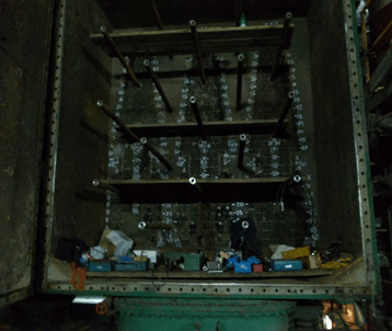
Condenser Water Box from a Large Power Station Condenser
Throttle Valves/Trip Valves
Due to steam throttling loses, it is desirable to have steam throttle valves (sometimes called ‘steam admission valves’) either fully closed, or fully open, when the turbine is in operation. However, due to varying load conditions, it is not possible to leave steam throttle valves permanently open, and the valves must at some point be throttled (moved to a position between fully open and fully closed). Because of this, there are normally a series of throttle valves which form nozzle banks.
As the turbine load increases, each nozzle bank moves from a fully closed to fully opened position, but only if the preceding nozzle bank is fully open. For example, steam enters nozzle bank 1 and each of the valves in nozzle bank 1 moves from the fully closed to fully open position in sequence. When all the valves in nozzle bank 1 are open, the process is repeated and the valves in nozzle bank 2 begin to open in sequence. Nozzle bank 3 will only begin to open if nozzle banks 1 and 2 are fully open, and only if the load on the turbine exceeds the amount of steam available through banks 1 and 2. In this way, it’s possible to reduce wear on valve components by having as many valves as possible in the fully closed or fully open position.
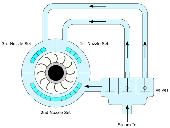
Nozzle Governing System
Steam flow is controlled by hydraulic valves equipped with stellite discs/plugs and seats; the stellite layer lends the plugs and seats very hard erosion resistant properties. As throttle banks operate at very high temperatures, the hydraulic control systems are prone to oil varnishing, a process that reduces the beneficial properties of the oil. For this reason, oil analysis of the hydraulic oil system should occur at scheduled intervals.
Some power plants operate for months without ever adjusting the steam throttling valves; this has led to valves ‘sticking’ and failing to actuate when desired. Throttle valves should be periodically stroked/throttled to ensure freedom of movement on both the hydraulic and steam side.
Prior to the steam admission valve there is normally an emergency trip valve which ‘slams’ shut (closes quickly) in the event of a critical situation occurring. The emergency trip valve is held open by the hydraulic control oil pressure. If the oil pressure decreases below a given setpoint, the emergency trip valve will actuate and the turbine will run to a standstill. Due to the size and speed of the turbine, it may take the turbine several minutes until it comes to a standstill e.g. 30 minutes.
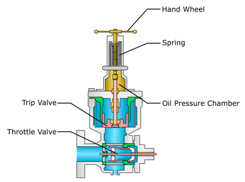
Combined Trip and Throttle Valve
Steam Turbine Designs
In an ideal situation, a steam turbine would be a single cylinder where steam is expanded from boiler pressure to a vacuum, depending upon which steam turbine design is used and on plant requirements. However, this setup is not practical as the length of the cylinder/casing would be quite long (assuming numerous turbine stages). Due to this excessive length, the turbine would suffer from problems associated with mechanical bending/distortion and mechanical expansion due to heat. To better deal with these problems, turbines are split into two or more separate cylinders. Each cylinder is named based upon the steam inlet pressure associated with that particular cylinder, these are:
- Low Pressure (LP) Cylinders
- Intermediate Pressure (IP) Cylinders
- High Pressure (HP) Cylinders
Each cylinder type has a different diameter in order to accommodate the associated steam turbine rotor. For example, LP turbine rotor blades are considerably larger than HP turbine rotor blades, thus a LP cylinder has a much larger diameter than a HP cylinder.
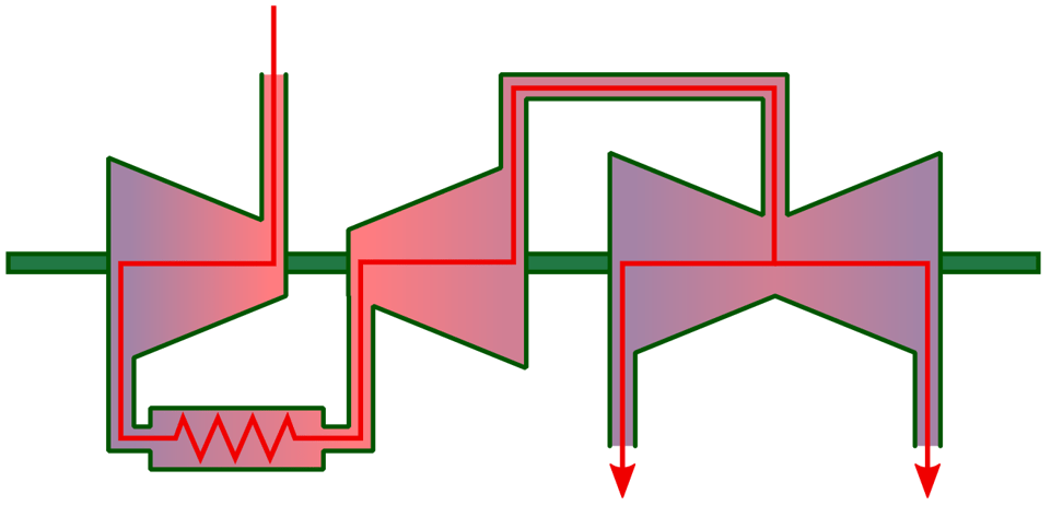
Another advantage when using separate cylinders is that each turbine rotor can be individually connected to an associated gearbox. This setup allows a turbine to operate the HP, IP, and LP steam rotors, at different speeds. Turbines with higher HP speeds and lower LP speeds are referred to as Tandem Articulated or Cross Compounded turbines; these types of turbine shafts are not directly coupled together.
Cross Compound Steam Turbine Arrangement
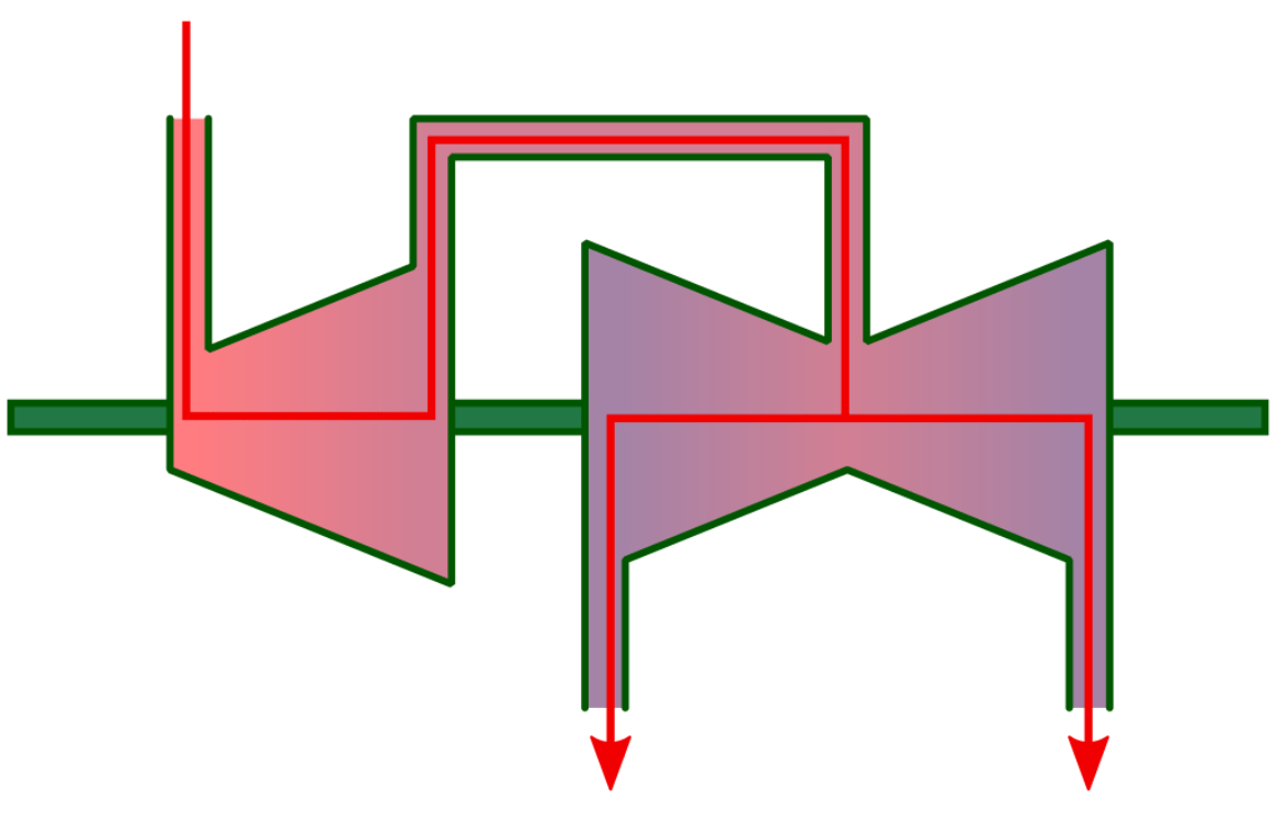
Steam turbine rotors are often mechanically coupled together to drive a large generator within a power station; this configuration is referred to as Tandem and these types of turbine are directly coupled together (they rotate at the same speed).
Tandem Compound Steam Turbine Arrangement
High Pressure (HP) Turbines
HP turbines operate initially at boiler pressure i.e. steam from the boiler is fed directly to the HP turbine. Because of the high pressure and resultant high velocity of the steam as it passes through the turbine, the highest efficiencies are obtained when the turbine is operated at higher speeds.
A turbine operating at optimum conditions will utilise rotating elements (rotor blades) that are designed to move at half of the steam inlet velocity. As the steam inlet velocity varies throughout the turbine, so too does the velocity of the blades. Correctly maintaining the relationship between steam velocity and blade velocity is achieved using pressure staging. Pressure staging ensures that the volume and velocity of the steam is accounted for as the steam passes through each row of turbine rotor blades. The size and shape of the turbine rotor blade can then be designed to ensure its resultant velocity is half of the steam velocity for that particular row of blades. Note that HP turbine blades are usually fully shrouded.
Typical HP Turbine Rotor and Casing
Intermediate Pressure (IP) Turbines
IP turbines are often installed within power stations but are not commonly used in other types of industrial plant. The main reason for the limited use of IP turbines is because they typically require a reheat system, which requires considerable additional floor space.
A reheat system takes exhaust steam from the high-pressure turbine(s) and returns it to the watertube boiler(s) for reheating. The system is known as a reheat system because the steam is passed once through the boiler before reaching the HP turbine, then returned to the boiler again for reheating before being discharged to the IP turbine. Reheating steam from the high-pressure turbine increases the overall plant efficiency.
Steam Turbine Reheat System
IP turbine blades are slightly larger than those on the HP turbine because they require a larger annular flow area. The larger flow area is due to the steam’s reducing pressure and increasing volume as it passes through each stage of the turbine. Due to the lower pressures, IP blades are not usually fully shrouded.
Low Pressure (LP) Turbines
LP turbines represent the final pressure stage before exhaust steam is discharged to the condenser (assuming a condenser turbine design is used).
The first stage blades of an LP turbine are normally shrouded whilst the larger final stage blades are not shrouded. Unless coupled to a lower speed section of the gearbox (if applicable), the larger blades can be more susceptible to cracking. Cracking typically occurs at the blade root and fire tree attachments due to the large centrifugal forces they encounter during operation. Due to these centrifugal forces, LP turbines are very sensitive to overspeed situations.
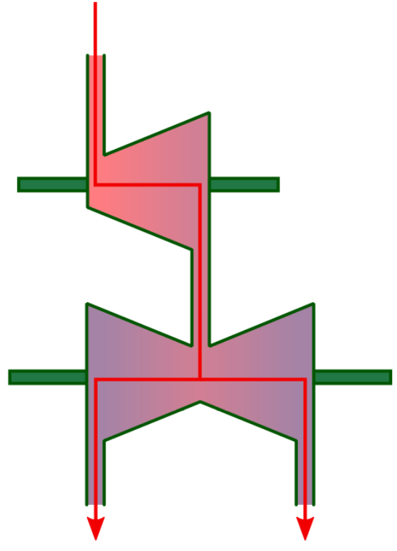
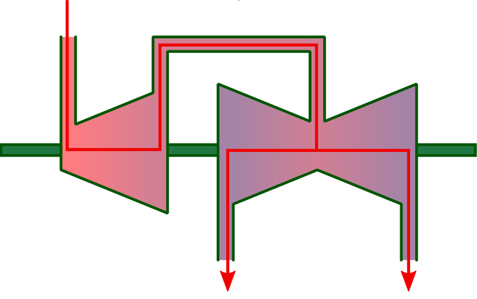
Due to the considerable reactionary forces on the LP turbine blades (due to their large size), larger LP turbine designs usually admit steam into the centre of the turbine; the steam then flow outwards through two opposing and identical stages. LP turbines that have this setup are designated double flow, or two flow, turbines.
Double Flow LP Turbine (shown on the right)
Double flow turbines are primarily used to equalise the thrust load from the opposing turbines, which minimises the size of the thrust bearings that the LP turbine requires. Sometimes, if a single casing LP turbine design is not possible, two smaller double flow LP turbines may be used. The use of smaller units reduces the centrifugal forces present on larger units and thus reduces the likelihood of cracking.
Other ways to minimise thrust loading include using a dummy piston. Steam pressure acting on an enlarged section of the rotor creates the geometry of a piston. The ‘dummy’ piston causes an equal opposing force to that created by the rotor thrust; thus, the two opposing forces cancel each other out.

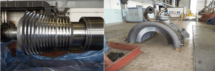
Typical Power Plant LP Turbine Casing and Double Flow Rotor
Steam Turbine Typical Operating Conditions
A typical power plant steam turbine will have steam entering the HP turbine at 180 bar (2610 psi), 540⁰C (1,000⁰F). Steam from the HP turbine is then returned to the boiler where it is reheated to 540⁰C (1,000⁰F) at approximately 45 bar (652 psi). The reheated steam is returned to the IP turbine and is exhausted to the LP turbine at around 10 bar (145 psi), 180⁰C (356⁰F). Finally, the LP turbine will exhaust to the condenser, which is held at around 720mm Hg (-0.95 bar/-13.77 psi) vacuum.
Summary:
- HP Turbine Inlet – 180 bar (2610 psi), 540⁰C (1,000⁰F).
- IP Turbine Inlet – 45 bar (652 psi), 540⁰C (1,000⁰F).
- LP Turbine Inlet –10 bar (145 psi), 180⁰C (356⁰F).
- Condenser Inlet – 720mm Hg (-0.95 bar/-13.77 psi) vacuum.
Condenser vacuum levels are dependent on effective condenser cooling. Poor cooling can have a considerable impact on the overall plant efficiency. For example, a typical loss of vacuum from 720mm Hg (-0.95 bar/-13.77 psi) to 702mm Hg (-0.935 bar/-13.59 psi) equates to roughly a 3% power loss.
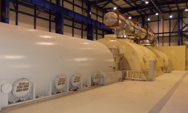
Typical Power Plant Steam Turbine and Generator
A typical marine steam turbine will operate at 65 bar (943 psi) and 515⁰C (959⁰F) at the HP turbine inlet. Steam is exhausted to the LP turbine at around 6 bar (87 psi) at 165⁰C (329⁰F). Steam is then exhausted from the LP turbine into the condenser at 720mm Hg (-0.95 bar/-13.77 psi) vacuum and very low steam temperatures. Note that due to the low temperatures of the LP turbine exhaust steam, the steam would be in a liquid state if exposed to atmospheric pressure.
A simple Curtis Wheel driving a high-speed centrifugal pump will operate at 60 bar (870 psi) or much less on de-superheated steam. Exhaust steam may be 3.5 bar (50 psi) and 150 ⁰C (302⁰F) (typical of a Coffin type feedwater pump turbine).
Turbine Bleeds
The term ‘bleed’ refers to the relatively small volumes of steam that are ‘bled’ from the steam system at various points within the system. Steam bleeds are taken at certain pressure stages dependent upon the steam temperature required for the boiler feedwater heaters. A typical turbine may bleed at 19 bar (275 psi), 9 bar (130 psi), 6 bar (87 psi) and 0.5 bar (7 psi), depending upon the feedwater heating arrangement. Non-return valves are used to control the flow through steam bleeds.
Water Ingress
Water ingress into a steam turbine is a major source of concern as it does considerable damage to turbine components. Typical components damaged due to water ingress include the fixed blades, moving blades, and diaphragm labyrinth seals.
It is critical that turbines are very carefully warmed through when starting. A methodical and slow warm-up procedure not only allows for differential expansion (axial and radial growth of the turbine due to its increased temperature), but also ensures there is no water in the steam lines. Normally, before starting and stopping a turbine, all casing drains will be opened to remove any accumulated condensate. In the steam inlet pipe there is also a steam separator (normally, but not always) which separates water droplets from the steam flow by causing a rapid change of direction of travel; the rapid change in direction causes moisture droplets to coalesce on the interior separator body surfaces and then drain out of the separator base.
Water content within the steam lines can be monitored by fitting thermocouples to the top and bottom of the steam lines/pipes. Water will be detected due to the temperature difference between it and the steam (the water will have a lower temperature).
Tip – If a thermocouple does detect water, it is often too late to prevent it entering the turbine unless the measuring points are located far away from the turbine itself.
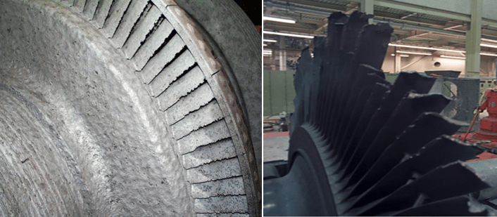
Water Damaged Turbine Moving Blades
Steam Turbine Systems
The oil systems (hydraulic and lubrication) of a turbine are critical not only for normal operation but also during power outages. Normally, the lubrication oil system is connected to the control oil system, depending on the turbine design.
Bearing lubrication oil is maintained at approximately 40⁰C (104⁰F) as this is an optimum temperature for the oil. Increasing the temperature of the oil above this temperature will reduce its lubrication and cooling abilities, which may lead to damage of the bearing and turbine components.
Lubrication and control oil systems are normally low pressure, high volume systems. The generator bearings, turbine bearings, turbine control valves, gearbox oil sprayers, coupling oil feeds, and other turbine components, may all use a common oil system.
The bearing oil system is connected to a trip valve, so that in the event of a supply failure (reduction in oil pressure), the turbine will trip/stop. Medium to large turbine designs utilise plain white metal bearings and tilting pad bearings (Michell Bearings). Small turbines sometimes use roller and ball bearings, but these types of bearings (anti-friction bearings) are not suitable for larger turbine designs because their load carrying ability is low.
Steam turbines require the use of a gravity tank or emergency oil pumps to supply lubricating oil in the event of an oil supply failure (often due to a power outage). A gravity tank (or tanks) is installed at the top of the power plant building and oil is constantly circulated through the tank to maintain the desired level. Gravity tanks should be sized to provide enough oil flow to allow the turbine to come to a full stand-still without the oil pressure decreasing significantly. However, a gradual turbine stop would require a large amount of oil and a correspondingly large gravity tank. To circumvent this problem, direct current (DC) electrically driven emergency lubrication oil pumps are used. The power to rotate the DC pumps is taken from batteries (flooded lead acid type typically), which operate independently of the main electrical bus board; this ensures the pumps will operate even if a power outage occurs. It is very important that a turbine’s emergency lubrication DC pumps are tested periodically, failure to operate when needed will most likely lead to significant damage of a turbine’s components.
Flooded Lead Acid Batteries
Condenser condensate pumps (extraction pumps) are critical for the safe operation of a condensing steam turbine; these pumps are used to return condensate from the condenser back to the deaerator via boiler feedwater heaters. It is important to constantly monitor the condenser condensate level, as too much condensate in the condenser hotwell may lead to several problems:
- High level - a reduction in condenser efficiency due to some of the heat exchanger surfaces being submerged by condensate.
- High level - poor control concerning maintaining of the condensate close to saturation temperature.
- High level - in extreme cases, condensate may enter the low-pressure turbine(s); this is more a problem for condensers installed on an axial plane with the turbine, not for turbines which have the condenser installed beneath them.
- Low level – cavitation within condensate pumps may occur. Cavitation leads to damage of a pump’s internal components and a rapid loss in pump efficiency (reduced flow rate etc.).
Critical Monitoring
Steam turbines are normally fitted with comprehensive monitoring and control systems. Extensive monitoring and control systems ensure turbines can be operated within their design limits, in a safe and efficient manner. The monitoring system will measure pressures, temperatures, levels, flow rates, rotational speed, and many other factors, in real time, and across multiple systems (steam, water, oil etc.). Some typical monitored parameters may include:
- Axial displacement of the turbine rotor.
- Condenser condensate levels.
- Exhaust steam temperatures
- Inlet steam temperatures.
- Lubricating oil pressure.
- Control oil pressure.
- Condenser vacuum pressure.
- Vibration levels.
- Overspeed detection - normally via a two out of three (2oo3) electrical voting system on modern turbine designs, or trip bolt/plunger on older systems which dump the control oil pressure.
Measured values will have associated alarms and trips depending upon their criticality. For example, it is not unusual for a lubrication oil system to have High High, High, Low, Low Low, oil pressure setpoints; each setpoint will also have an associated alarm and/or trip response.
Steam Turbine Efficiency
Unless the load (generator or pump etc.) can operate at high speeds, the associated turbine normally connects to the load via a reduction gearbox. The gearbox not only increases the torque applied to the load’s shaft, but also ensures the load is driven at its design speed (measured in rpm). From an efficiency perspective, a gearbox is an added weight, represents additional maintenance, additional financial expense (both initially and operationally), and it increases friction (which causes an overall reduction in machinery efficiency). If a gearbox is installed, it is not possible to operate the turbine without the gearbox, thus failure of either the gearbox or turbine will result in a total failure of the unit. For this reason, a gearbox represents an additional potential failure mode.
If using a steam turbine to drive/rotate a ship’s propeller, there needs to be some way of driving it astern (reverse direction). This is normally achieved with a separate turbine mounted on the back of the low pressure (LP) turbine; this setup causes efficiency losses due to condenser conditions during heavy or prolonged operation.
In many applications, steam turbines have been replaced by diesel engines. Diesel engines are favoured because they do not require the large supporting water and steam systems that steam turbines require. However, steam turbines have a high operating efficiency, and this can be further increased if they are utilised within a favourable industrial setting. For example:
- Steam turbines are ideal for liquid natural gas (LNG) carries/ships because onboard boilers can burn any natural gas that does not remain in condensed form; this gas is known as ‘boil off’. The boilers provide the necessary steam for the steam turbine(s).
- Combined cycle power plants reclaim waste heat from combustion turbines or from industrial processes that generate significant waste heat e.g. nitric acid plants. Waste heat is reclaimed using heat recovery steam generators (HRSGs). HRSGs provide the necessary steam for the steam turbine(s).
- Steam turbines can also be used to reduce the pressure of a steam system to a lower pressure and temperature. This is useful if other parts of the industrial plant require service steam for heating and sterilisation purposes.
- Large boiler feedwater pumps are also often steam driven, which reduces the electrical load of the power plant whilst increasing the overall plant efficiency.
Related Online Engineering Courses
Introduction to Steam, Boilers and Thermodynamics
How Steam Turbine Condensers Work
Sub-Critical, Supercritical, and Ultra-Supercritical Boilers
Heat Recovery Steam Generators Explained
How Coal Fired Power Stations Work Part 1
How Combined Cycle Power Plants Work
How Flue Gas Desulphurisation Works
Electrostatic Precipitators (ESP)
Additional Resources
https://petrotechinc.com/how-does-a-steam-turbine-work
https://en.wikipedia.org/wiki/Steam_turbine
https://www.explainthatstuff.com/steam-turbines.html