

What are deaerators?
Deaerators are pressurised feedwater tanks also referred to as open feedwater heaters. Deaerators are critical components of many steam systems and have several functions:
- Remove non-condensable gases from boiler feedwater.
- Increase the temperature of makeup water as it enters the system.
- Increase the temperature of condensate prior to it entering the boiler.
- Provide a storage capacity of treated feedwater.
There are two common deaerator designs, the spray type and tray type (also known as the spray-tray type). A variation of the spray type is the spray-scrubber type.
Deaerator
All medium to large steam systems require a deaerator to reduce the levels of dissolved oxygen (O2) and carbon dioxide (CO2) in the boiler feedwater, both of which will cause corrosion to boiler system components if not removed.
Deaerators achieve deaeration by raising the temperature of the feedwater, which reduces the solubility of the non-condensable gases i.e. the gases are released from the water. Once the dissolved gases have been released, the likelihood of corrosion is drastically reduced and the feedwater can be fed to the boiler.
The Deaeration Process
The process of deaeration may occur mechanically or chemically. Deaerators provide the mechanical solution whilst chemicals provide the chemical solution.
A typical deaerator will remove almost all dissolved oxygen and CO2, with the remainder being removed by oxygen scavengers (sodium sulphite, hydrazine etc.) and CO2 scavengers (neutralising amines, bicarbonate etc.).
Most deaerators are designed to reduce dissolved oxygen levels to 0.05 cc/l (7 ppb), with oxygen scavengers removing the remainder.
Why remove oxygen and carbon dioxide?
Corrosion of boiler components exposed to water will occur if dissolved oxygen is present, or, the water pH is low.
Boilers and their ancillary systems are mostly constructed of carbon steel. As steel is iron based and oxygen reacts with iron to form red iron oxide (rust), the potential for corrosion is high. For this reason, it is imperative that the boiler feedwater dissolved oxygen content is as low as possible.
The amount of dissolved carbon dioxide in water dictates how acidic the water is. The greater the dissolved CO2 in the water, the lower the water’s pH i.e. the more acidic the water is. Low pH values will cause corrosion of boiler parts and consequently must be avoided. A typical boiler will operate with a pH value of between 8 to 11 (approx.), but this depends heavily upon the boiler system.
The corrosion rate is not only dependent upon the dissolved oxygen and dissolved carbon dioxide levels, it is also dependent upon temperature. High temperatures cause high corrosion rates, even with low amounts of dissolved gases. For this reason, low temperature steam systems can tolerate much higher levels of dissolved oxygen and carbon dioxide than high temperature systems.
What is corrosion?
Corrosion can be classed as general, localised, or stress.
General corrosion occurs within a single system component, or throughout the entire system, and is usually considered light corrosion. A thin red oxide layer covering the water side heat transfer surfaces of a boiler is an example of general corrosion. General corrosion is often red (iron oxide) or black (magnetite oxide) in colour. If waterside metal surfaces are red, the metal is corroding, and corrective action must be taken. Black surfaces are desired as magnetite oxide deters further corrosion.
Localised corrosion relates to corrosion within a specific area; this type of corrosion is usually moderate to extensive. Oxygen pitting (small holes in a metal surface caused by corrosion) is an example of localised corrosion. Oxygen pitting often occurs wherever the water and steam phases meet (waterline in boiler or deaerator), or under sediment that has settled somewhere in the system.
Stress corrosion occurs in high stress point areas. High chloride levels, thermal shock and high pH, can all cause stress corrosion. Stress corrosion caused by high pH levels is referred to as caustic embrittlement. Stress corrosion caused by thermal shock is referred to as fatigue corrosion.
Deaerator System
Boilers generate steam which is delivered to the process. Some of the steam transfers its energy to the process and condenses; the resultant water is termed condensate. Condensate is gathered throughout the steam system and is returned to a central storage tank, this is either an atmospheric feedwater tank, or a pressurised feedwater tank (deaerator).
Spray Deaerator
Enjoying this article? Then be sure to check out our Engineering Video Courses! Each course has a quiz, handbook, and you will receive a certificate when you finish the course. Enjoy!
Makeup water replaces water losses within the system. Water losses may be an unavoidable part of the process e.g. steam cleaning of glass bottles in the edible food industry, or, may be due to leaks or evaporation losses etc.
When condensate reaches the feedwater tank, it is termed feedwater, as it is then fed to the boiler. Similarly, when makeup water enters the feedwater tank, it is thereafter termed feedwater.
Systems with low condensate returns must continually add large amounts of makeup water. Continuously adding makeup water introduces more untreated water to the system compared to when reusing condensate that has already been treated. For these reasons, a deaerator is much more likely to be installed on a system with low condensate returns than one with high condensate returns. It should be noted that systems with low condensate returns will have larger operating costs due to higher water consumption, higher heat/energy consumption (water has to be heated before entering the boiler) and higher chemical treatment consumption.
The solubility of dissolved gases in water reduces as the temperature of the water increases. In order to raise the boiler feedwater temperature, low pressure steam is supplied. The steam transfers its heat to the feedwater until the feedwater approaches its saturation point (boiling point). As the water approaches its saturation point, the dissolved oxygen level approaches zero. In power plant, the steam supplied is often waste steam from the steam turbine(s).
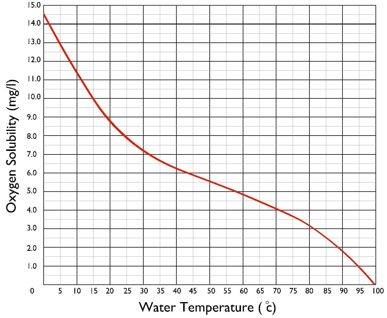
Gas Solubility Reduces as Temperature Increases
Dissolved gases released by the deaeration process are vented to atmosphere along with trace amounts of steam. A typical vent will use a plate with an orifice (hole) to control the rate at which gas is vented. If the orifice is too large, steam will be vented, which reduces the overall plant efficiency (because of the reduction in steam cycle efficiency) and drives up costs. If the orifice is too small, some gases may return to the feedwater, which is also undesirable.
Chemical dosing occurs on the makeup inlet line, within the deaerator, or between the deaerator and boiler. The chemicals needed, their quantity, and where dosing should occur, depend upon the system design. For example, makeup water supplied from a reverse osmosis (RO) plant will have a low pH and should be treated before it enters the deaerator.
Deaerator Components
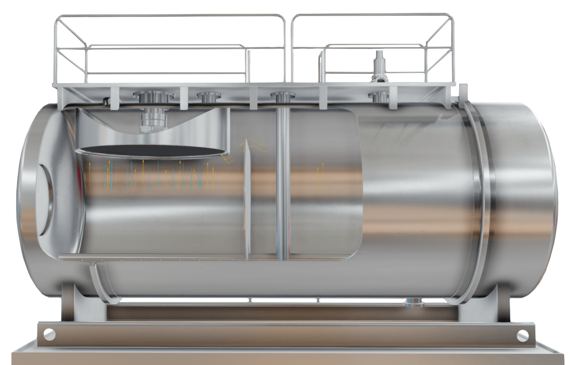
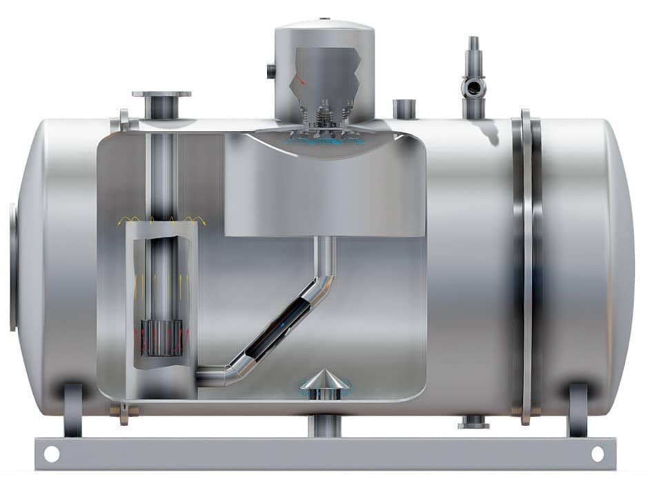
A deaerator is an unfired pressure vessel. Deaerators are typically manufactured from carbon steel, although some industries -such as the pharmaceutical industry- use stainless steel. The pressure vessel is cylindrical in shape with as few welds and penetrations as possible.
Attached to the deaerator are connections to the various systems it serves and other appendages required to operate the deaerator. Common deaerator system connections and appendages include:
- Low pressure steam inlet.
- Makeup water inlet.
- Condensate inlet.
- Feedwater outlet.
- Safety relief valve (SRV).
- Water column or siphon.
- Level sight glass.
- Level control sensor.
- Drain line (for maintenance).
- Overflow pipe (non-return design).
- Chemical injection point.
- Flanges for gauges (pressure and temperature gauges etc.).

Tray Deaerator Connections
A pressurized deaerator will operate at approximately 5 psi at 230°F (imperial), or 0.4 bar at 105°C (metric). Deaerator feedwater will be maintained as close to the saturation temperature as possible in order to reduce the level of dissolved gases as much as possible, but without the water changing phase to steam. If the feedwater exceeds its saturation temperature, it will begin to form steam and will either condense, or be vented to atmosphere, both of which are not desired.
How Deaerators Work
The below video is an extract from our Introduction to Steam, Boilers and Thermodynamics Online Video Course.
There are two common deaerator designs, spray and tray (spray-tray). Each design has its own operating characteristics. Regardless of the design employed, both deaerators designs:
- Maximize the contact surface area between the water and steam to obtain a high heat transfer rate.
- Rely upon direct contact between the steam and water (usually tray, spray, bubbling, or a combination of these).
- Employ spray nozzles.
- Utilize steam as the heat source.
- Agitate the water using steam.
- Can be mounted onto the top of a feedwater storage tank.
- Are often manufactured from the same materials.
- Are open/vented to atmosphere.
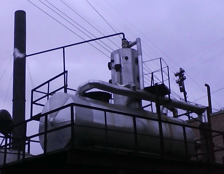
Although spray deaerators are often mounted to the top of feedwater tanks, they can also be installed within the feedwater tank. A deaerator mounted above a feedwater tank will appear either as a small tank connected by a pipe to the feedwater tank, or, as a dome or vertical column, mounted directly to the feedwater tank.
Makeup water will pass through the deaerator when it enters the system. Condensate may or may not pass through the deaerator depending upon its condition when returned to the feedwater tank. Deaerator designs vary because each steam system has unique requirements.
How Tray Deaerators Work
Water enters the deaerator and fills the water box. The water box is a temporary holding area that ensures water is fed evenly through a series of spray nozzles, then into the deaerator.
Each spray nozzle acts as a non-return valve and will close if the water box has insufficient water pressure. To ensure long life, spray nozzles, the surrounding spray area and the trays, are all constructed of stainless steel.
Spray Tray Deaerator
Once the water has passed through the spray nozzles, it comes into direct contact with the steam. The steam flows in a counter direction to the water. As the steam heats the water, the dissolved gases are liberated. The quantity of dissolved gases present reduces as the water cascades down through each successive tray. The upper trays are referred to as heating trays, or first stage trays. The lower trays are referred to as deaeration trays, or second stage trays. The water then exits the tray area and is discharged to the feedwater tank.
Dissolved gases and some steam are constantly discharged through the vent. A typical deaerator will vent between 5% to 15% of the steam that passes through the deaerator. As steam costs money to generate, it is beneficial to vent as little steam as possible.
Approximately 90% to 95% of deaeration occurs within the spray area with much of the remainder occurring in the tray area. Mechanically deaerated water is usually designed to lower the oxygen content to 7 parts per billion (ppb). Any remaining oxygen in the feedwater is stripped using oxygen scavenging chemicals (sodium sulphite, hydrazine etc.).
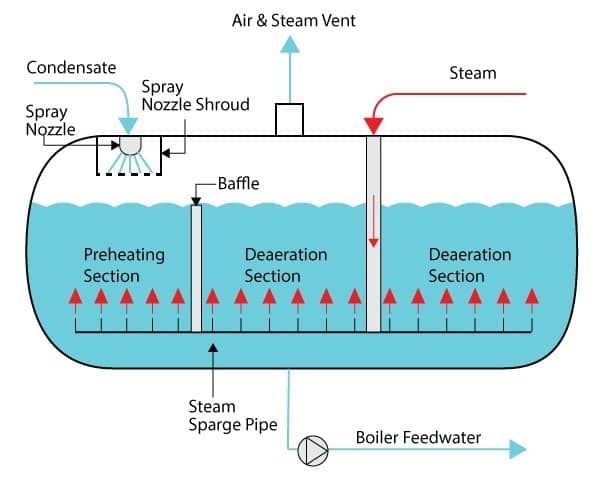
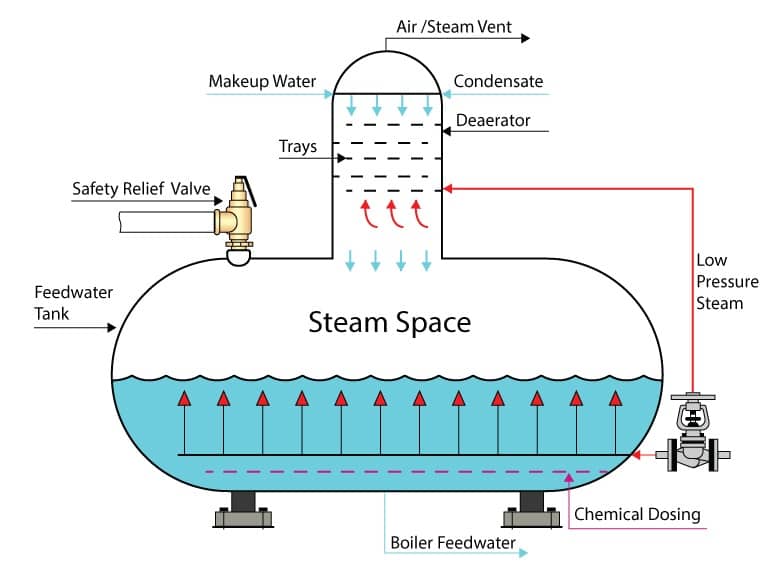
How Spray Deaerators Work
Condensate and makeup water enter the water box directly above the spray nozzles; the spray nozzles are spring loaded. Water pressure causes the nozzles to open and water is sprayed into the deaerator. Spraying the water into the deaerator ensures a large contact surface area between the water and steam, which ensures good heat transfer between the two fluids (fluids are defined as either liquid or gas).
Spray Scrubber Deaerator
Water exits the nozzles and passes through a large perforated circular tray before joining the water in the feedwater tank. A submerged steam sparge/sparger pipe distributes steam to the preheating and deaeration sections of the deaerator. The steam heats the water to within 2°C (approx. 4°F) of its saturation temperature to ensure as many condensable gases are liberated from the water as possible.
The heated water then passes around a baffle plate to reach the deaeration section, and is discharged as heated, deaerated, feedwater.
How Spray Scrubber Deaerators Work
Spray scrubbers function in a similar manner to spray deaerators, but they have a scrubber installed. Water enters a water box, is sprayed through spray nozzles, then drains through a tray and is directed to a scrubber.
Scrubbers utilise steam to agitate (using steam bubbles) and heat water after it leaves the spray area of the deaerator. Close contact with the steam ensures good heat transfer and rapid liberation of dissolved gases. The deaerated water then collects in the feedwater tank and is ready for use as boiler feedwater.
Spray Scrubber Deaerator
Design Considerations
The type of deaerator chosen for a steam system is heavily dependent upon the system. Some systems are effectively closed-loop systems which require very low amounts of makeup water (1-3%); other systems require large amounts of makeup water. The temperature of the returned condensate is also a factor that must be accounted for.
Steam System Comparison
A power plant steam system providing steam to steam turbines has the following characteristics:
- Operates within a closed system and so requires little makeup water.
- Is not exposed to atmosphere, so there is little chance of gas entrainment.
- Returns condensate at a temperature near the saturation point of the water and thus contains low amounts of oxygen and carbon dioxide.
A paper pulp plant steam system has the following characteristics:
- Operates within an open system with condensate returns typically less than 50%. Consequently, makeup water requirements for the system are typically 50% or more.
- Is exposed to atmosphere, so gases will become entrained in the condensate.
- The reduction in pressure and temperature is large, which increases the solubility of gases in the water.
Deaerator Entry Point
Condensate within a closed system may pass through spray nozzles as it enters the deaerator, or it may not. If the condensate is close to its saturation point, then it may be delivered directly to the feedwater tank rather than through the deaerator.
Makeup water is almost always passed through spray nozzles as it enters the deaerator, this is to reduce the risk of thermal shocking and to ensure that all dissolved gases are removed upon entry into the system.
Large Condensate Returns
The temperature, pressure and deaerated condition in which the condensate is returned is important, but the volume that is returned is important for several reasons. Systems with proportionally large condensate returns have the following advantages:
- Utilise little makeup water, leading to a reduction in operating costs.
- Receive condensate that is almost always warmer than makeup water, so less heat must be applied for it to reach its saturation temperature. This yields a greater system thermal efficiency and reduction in operating costs (less heat required means less fuel required for the boiler).
- Less chemical dosing required because chemicals are not dumped from the system. Chemical water treatment is not cheap, so water that has already been treated should remain in the system for as long as possible.
Feedwater Tank Size
Feedwater tanks connected to deaerators provide a stored amount of treated boiler feedwater that can be used to cope with fluctuations in steam demand. A typical boiler feedwater tank will hold enough water to feed a fully loaded steam system (boiler or boilers) for approximately 10 to 15 minutes. For critical systems, the reserve is increased and/or an additional deaerator will often be installed. Building redundancy into the system is referred to as:
n+1 system redundancy
Where n is the quantity of machinery or equipment required for safe operation of the plant and the number indicates the quantity of the reserve. Nuclear power plants often operate with n+2 on all critical plant equipment.
Feedwater Tank Location
Boiler feedwater pumps are installed directly after the boiler feedwater tank. These types of pump are often centrifugal, or multistage centrifugal in design. Centrifugal pumps are not usually self-priming and cannot pump gases, it is therefore imperative that the feedwater supplied does not change state/phase to steam.
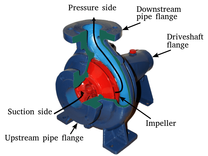
Centrifugal Pump
Feedwater is stored at a temperature close to its saturation point to ensure very low amounts of dissolved gas are present. If the system pressure reduces, the water may turn to steam, and this would cause the pumps downstream of the tank to lose suction (in extreme cases). For this reason, feedwater tanks (and deaerators) are installed at a higher elevation in the plant than the pumps. As water leaves the feedwater tank, its pressure increases and the risk of the water changing state reduces.
Aside from the risk of losing suction, steam bubbles within the water may form and collapse as they pass through the pump impeller. The forming and collapsing occurs due to the difference in suction and discharge pressure. Whilst this condition is relatively harmless in small amounts, it becomes a problem if the frequency increases i.e. thousands of times per second. As the vapour bubbles collapse, they cause damage to the surrounding metal surfaces and gradually erode the parts. Over time, an impeller can literally be ‘eaten’ away. This phenomenon is known as cavitation.
If a pump is suffering cavitation, it is easily identifiable because it will sound as if marbles are passing through the pump. See the Introduction to Centrifugal Pumps course, or associated handbooks if you would like to learn more.

Cavitation
Maintenance
Deaerator maintenance should only ever be conducted by trained professionals. An annual boiler inspection is a statutory requirement in most industrialised countries. This annual inspection serves as an ideal opportunity to perform deaerator maintenance tasks.
Maintenance tasks associated with deaerators vary depending upon design, but some common tasks should be performed on all deaerators:
- Visual inspection of all internal deaerator and feedwater tank surfaces. The focus of the inspection is mostly visual, with an emphasis of locating any cracks, scale and/or corrosion. The water to steam interface (location of water line in feedwater tank) is often an area where corrosion occurs.
- Non-destructive testing (NDT) of welds prone to cracking. NDT techniques used are often dye penetrant testing (PT), shear wave ultrasonic testing (UT); magnetic particle testing (MT) and/or wet fluorescent magnetic particle inspection (WMFT).
- Sedimentation, or any accumulation of materials within the feedwater tank should be removed and a sample sent to a laboratory for testing. The source of the material should be identified.
- Dismounting of deaerator fittings and mountings (as needed). Gauges should be checked for accuracy. Manifolds or pipes connected to instrumentation should be checked for restrictions and blockages.
- Overflow devices and relief devices should be checked, calibrated, or replaced as needed.
- Level floats and level sensors should be function tested to ensure both the mechanical and electrical circuits are operating as intended.
- Spray nozzles should be checked for corrosion and the springs hand tested to ensure their operation. A true test of the spray nozzles can only be performed when testing under hydrostatic pressure.
- Leaking flange connections or pipe connections should maintained.
In addition to the maintenance tasks mentioned above, additional more frequent tasks should include:
- Daily inspection of the deaerator and feedwater tank installation. The inspection should be non-evasive. Inspectors are performing a ‘senses inspection’ with the intention of identifying any abnormalities e.g. leaking gaskets, loud noises, false gauge readings etc.
- Daily visual inspection of the vent to ensure constant regulated flow.
- Daily visual inspection and log entries of the deaerator pressure and temperature. Trending data over time allows for anomalies and problems to be quickly identified.
- Frequent checking of the boiler feedwater tank level.
- Frequent, or constant, boiler feedwater analysis. High levels of oxygen and/or carbon dioxide indicate that the deaerator is not functioning as intended.
Irrespective of the deaerator design, the manufacturer should always be consulted when creating a deaerator maintenance plan. Significant documentation (manuals, spare parts catalogue etc.) is also provided from the manufacturer as part of the deaerator purchase.
Additional Resources
https://en.wikipedia.org/wiki/Deaerator