


Introduction
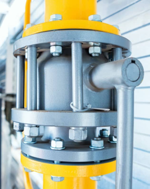
Flanges offer a mechanical means of joining pipes, fittings (elbows, tees etc.), and valves. Compared to welds, flanges are a non-permanent type of joint that can be easily assembled and disassembled (ideal for systems that require maintenance). Flanges are installed via welding, screwing, or lapping, and they are the second most popular joining method after welding.
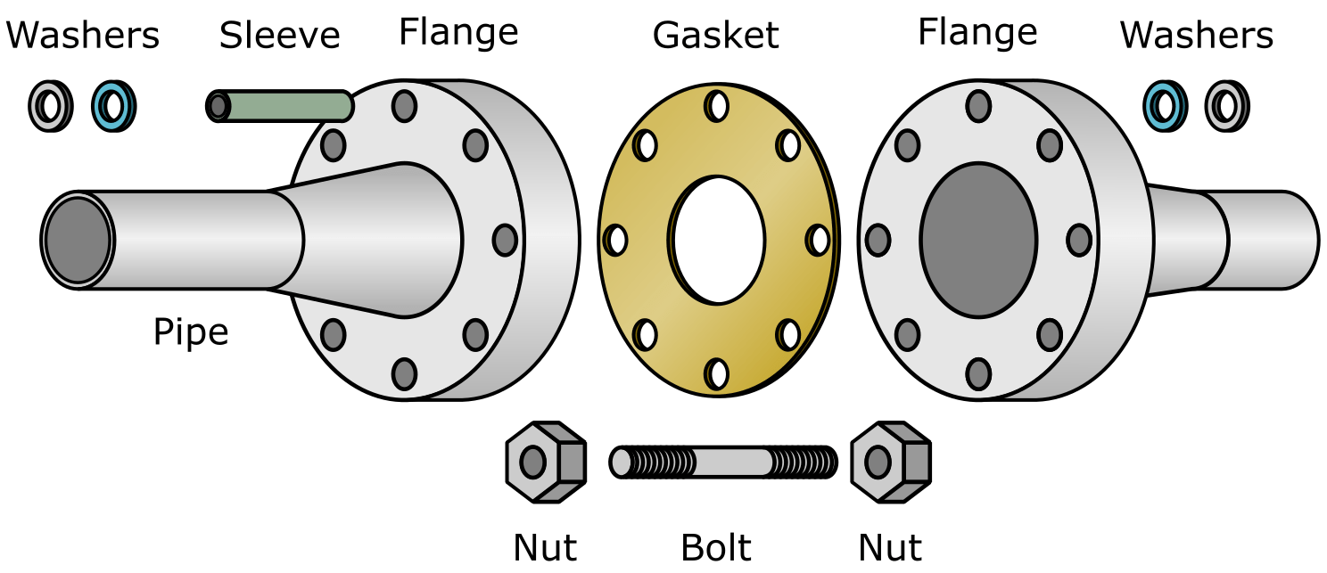
- Flange (blade, hub).
- Gasket (metallic, composite, or non-metallic).
- Fasteners (nuts, bolts, or studs).
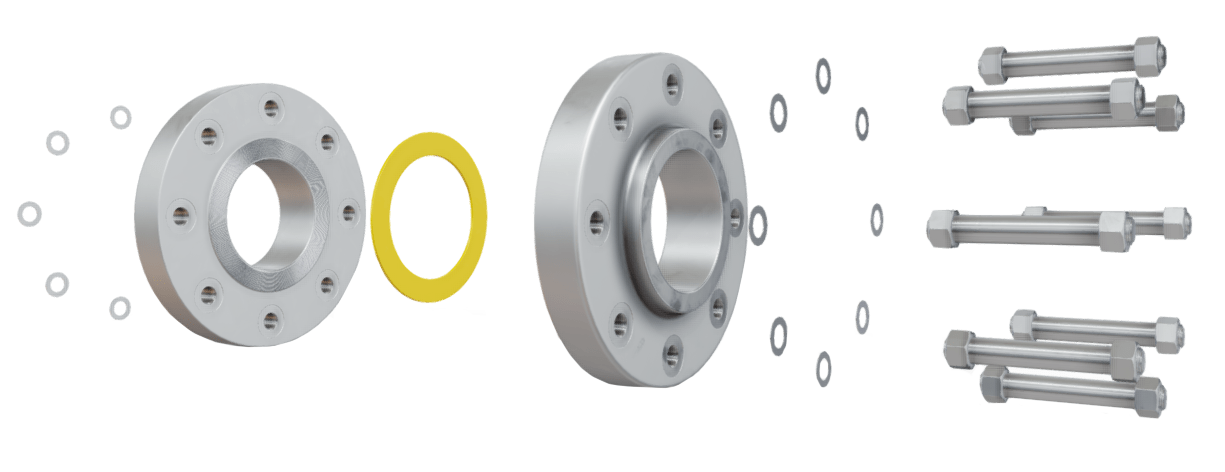
Flange Assembly
Are you enjoying this article so far? Then be sure to check out our Flange Fundamentals Video Course. The course has over five hours of video content, a 52 page colour illustrated handbook (this article is an extract from the handbook), a quiz, and you will receive a certificate of completion when you finish the course. Enjoy!
Flange terminology
Flange terminology and nomenclature can be confusing due to the similar terms, definitions, and phrases that are used. To make the learning process easier, readers should clearly understand the following terms:
- Flange types – refers to the flange design. Examples of flange types include the welding neck (weld neck), slip-on, socket weld, threaded, blind flange and lap joint type flanges. Flange types are selected based on the temperature and pressure requirements, and are identifiable by their geometry.
- Flange faces – refers to the area used for sealing of the flange; a gasket is usually installed between the two opposing flange faces. Examples of flange faces include the flat, raised, ring-type joint (RTJ), lap joint, tongue and groove, and male and female designs.
- Flange surfaces – refers to the condition of the flange face sealing surface. A flange face surface may be smooth, or serrated1. The smoothness of a flange face surface is defined by its Roughness Average (Ra) or Arithmetic Average Roughness Height (AARH).
All of the afore mentioned topics will be further discussed. It is important to realise that there are many aspects that influence not only what flange type is chosen for a particular application, but also what face and what surface. For example:
- Certain systems may require welded joints that can be easily inspected (this is not always possible with certain flange types).
- Certain flange faces may not be suitable for higher pressure systems because the maximum sealing pressure is too low (flat face designs).
- Certain materials will tend to have poor finishes that yield a correspondingly rough sealing surface; these rough surfaces require a gasket if a leak tight seal is to be achieved e.g. cast-iron flanges.
When selecting a flange, the material is chosen to meet process requirements first, whilst the temperature and pressure requirements are then met based on the material chosen.
1‘Serrations’ are machined grooves cut into the surface of a flange’s face. Gasket material flows into the grooves, which results in a more reliable seal being obtained; the grooves also help hold the gasket stationary.
Bolted, Threaded and Welded Joints
Flanges are a type of bolted joint. Other common types of joint include threaded joints and welded joints.
- A bolted joint requires a flange and fasteners (nuts, bolts, or studs).
- A threaded joint requires a male and female screw thread, the male thread screws into the female thread.
- A welded joint is made using a weld (the process of melting/fusing metal by applying heat).
Bolted Joint
The type of joint used depends on many factors, including pressure, temperature, type of process fluid, operating characteristics of the system, and the surrounding environment. A bolted joint may be used if:
- Other types of joint are not suitable e.g. welding may not be possible within areas that pose a fire or explosion risk (Ex areas); this is mostly a concern for an already operational piping system, not one that is under construction.
- A machinery item must be disconnected from the service line in order that maintenance or replacement of the machine can occur.
- Quick field assembly is required using only basic hand tools.
- The item (e.g. tank, pipe, machine) to which the flange is connected must be frequently maintained; it is quick and easy to disassemble and assemble a flange, but not a weld.
Some of the main disadvantages associated with a bolted joint include:
- Insulating a bolted joint (thermal insulation) costs more than insulating a threaded or welded joint.
- Bolted joints require more physical space than threaded or welded joints.
- Each bolted joint represents an additional leakage point (even if assembled correctly).
As a general rule, threaded joints are suitable for lower pressure and temperature applications only, whilst bolted and welded joints are suitable for higher pressure and higher temperature applications. If a threaded joint must be leak tight, and leakage cannot be tolerated, it can be seal welded. The seal welding technique is only used for higher service pressure conditions and is not an ideal solution because it creates a stress concentration point which will be prone to fatigue failure.
The advantage with welded joints is that the weld can be proved using non-destructive testing (NDT) techniques e.g. penetrant testing, ultrasonic testing, magnetic particle testing, hydrostatic pressure testing etc.; proving a flange -and flange gasket- is more difficult.
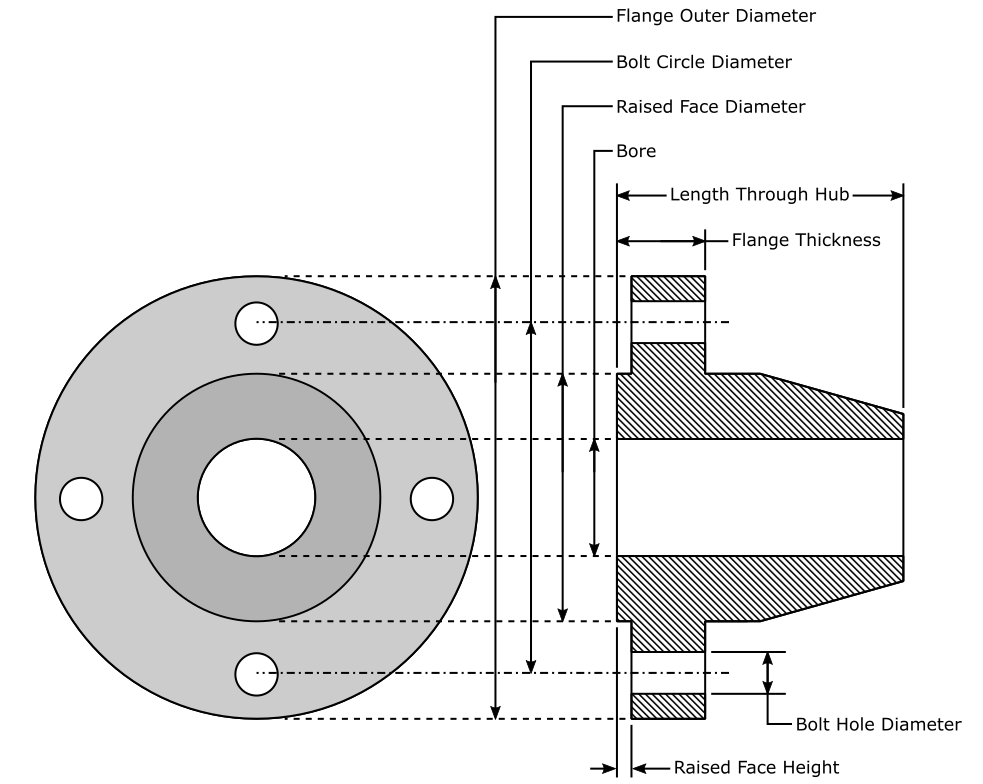
Flanges Construction
Flanges are split into two main areas, the ‘blade’, and the ‘hub’.
- The flange blade encompasses the area where the bolts penetrate through the flange and the flange face.
- The flange hub is the area that accommodates the pipe which attaches to the flange.
To ensure no leaking between the mating2 flanges occurs, gaskets are used. It is possible to mate two metal flanges together without the use of gaskets, but sealing is difficult and can only be achieved with specially designed flanges.
The end connection specifies how the flange is connected to its accompanying pipe (threaded connection or welded).
Flange Design
2Mating – refers to the pressing together of two opposing flange face sealing surfaces.
How Flange Work
A flange is created when two opposing surfaces are intentionally pressed together in order to create a leak tight seal. To obtain a seal, force must be applied and maintained to each of the opposing flange faces. As many flange faces have manufacturing imperfections (scratches, dents, pits etc.), it is necessary to put a softer material between the two mating sealing surfaces to obtain the seal; this softer material is the gasket.
Flange Assembly
Basic Flange Math
To understand how flanges work, we must first understand the concept of pressure. Pressure is defined as:
Pressure = Force / Area
P = F / A
Flanges seal because pressure is applied to the mating sealing surfaces; this pressure is known as the ‘gasket compression’ or ‘sealing pressure’. The applied pressure causes the two faces to either:
- Crush a gasket between the two mating faces.
- Press the two mating faces against each other.
In the gasket example, the gasket is deformed due to the pressure applied; this deformation causes the gasket to ‘flow’ into any surface imperfections that may be present on either sealing face. Because the surface imperfections have been filled by the gasket material, leakage is no longer possible.
The second example assumes no gasket is present and that two flange faces are pressed together. It is hard to create a leak tight seal using this method, although it is possible if the surfaces are well machined and very clean. The sealing pressure applied will often need to be significant, as the flange surface may be manufactured from metal, which does not easily deform under pressure (material and flange class dependent). Metal to metal flange face sealing is expensive and thus not common.
To create the necessary sealing pressure, the variables of force and area can be adjusted.
- Force refers to the tightening torque (bolting load) applied to the mating flange faces when the nuts on a flange assembly are tightened. Force (F) depends upon the torque (T) applied, torque friction (K) and nominal bolt diameter (D). The force described is classed as ‘bolt pretension’ or ‘bolt preload’, or ‘bolt prestress’, and is represented by the equation F = T/(KD)
- Area refers to the size of the sealing face area.
The amount of pressure on the flange sealing faces corresponds to the amount of force applied when tightening the flange assembly. Thus it is possible to regulate the pressure by adjusting the amount of effort that is exerted when tightening the bolts during flange assembly.
The sealing area of a flange cannot be as easily adjusted as the force used during assembly. A larger sealing face requires more force to obtain a certain amount of pressure, compared to when using a smaller sealing face. The below example highlights this point, but without the use of units.
Example
A given flange assembly requires a pressure of 10 to seal. This can be achieved by applying a lot of force onto a small sealing face:
Pressure = Force / Area
10 = 40 / 4
Or, it is possible to decrease the size of the sealing face (area) and thus reduce the amount of force required to create the same amount of pressure3:
10 = 20 / 2
The relationship between pressure, force, and area, can be briefly summarised:
Decreasing the sealing face area leads to a decrease in the force required to create a given amount of pressure.
Increasing the sealing face area leads to an increase in the force required to create a given amount of pressure.
The amount of force that can be applied to a flange assembly is limited because of problems relating to physical strength (nuts are often hand-tightened), gasket blow-out4, and stripping5 of the flange bolt threads; but these problems can be overcome if the size of the sealing face is reduced. The type and size of the sealing face used will be dictated by relevant piping standards once the temperature and pressure rating of the flange is known.
Based on what has been discussed in this section, it can be determined that flanges required to seal at higher pressures, have smaller sealing faces. It is possible for a viewer to guess the pressure at which a system operates by visually inspecting the flange sealing faces e.g. large flange sealing faces indicate low pressure systems.3Standards such as ASME B16.5 and B16.47 dictate the size of the sealing face required.
4Refers to the expulsion of the gasket from the sealing face due to pressure; this usually occurs due to overtightening of the flange during assembly.
5Refers to the removing of the threads from the stud or bolt; the result is a spherical piece with no screw threads.
Flange Defining Factors
Flanges are categorised based upon certain criteria, and these categories are usually defined by relevant piping standards and specifications (discussed later). A flange is defined by
- Type – the geometry of the flange as a whole. Welding neck, slip-on, and socket weld, are examples of different flange types.
- Face – the sealing area of the flange. Flat face, raised face, and ring type joint, are examples of different flange faces.
- Standards and Specification – flanges are manufactured to comply with given standards and specifications. Standards and specifications dictate the dimensions, geometry, schedule, and material, of a given flange (to name a few factors).
- Dimensions – the dimensions of a flange’s hub, face, blade etc. Dimensions depend upon nominal pipe size (NPS) and the pressure class required for a given application.
- Nominal Pipe Size (NPS) – a dimensionless unit of measurement defining the size of the item (pipe, fitting etc.) that connects to the flange.
- Pressure Class – the pressure-temperature rating of the flange for a given material. Despite the name ‘pressure class’, this factor is material and temperature dependent.
- Material – the material from which the flange is manufactured e.g. cast iron, carbon steel, stainless steel etc.
- Schedule (SCH) – a pipe’s thickness/schedule. The schedule of a pipe is relevant only for welding neck and lap-joint flanges because the schedule of these flanges must match the associated pipe schedule to which they are connected. The other flange types either slide partly into, screw into, or penetrate through, their associated flange, thus the flange schedule does not need to match the pipe schedule. The schedule is relevant for swivel-ring flanges, but these have limited application and will not be discussed further.
All of the aforementioned bullet points will be discussed in a logical order in the coming sections. For now, it’s important to realise that flanges are not unique items. Flanges are manufactured for a specific purpose, with many design factors already considered. Should a flange ever fail, the exact same flange can -theoretically- be ordered to replace its predecessor6; this has significant real-world benefits, which will be discussed later in the Standardisation section.
6A root cause analysis (RCA) should be conducted on any flange that has failed unexpectedly. If the cause of failure is not determined, the same failure may occur again even with a new flange.
Flange Types, Faces, and Surfaces - Explained!
This video is part of our Piping Flange Fundamentals Video Course
Related Online Engineering Courses
Introduction to Valves (short course)
Introduction to Centrifugal Pumps
How Multistage Centrifugal Pumps Work
Plate Heat Exchanger Fundamentals
Introduction to Heat Exchangers
Refresher How Plate Heat Exchangers Work
Sub-Critical, Supercritical, and Ultra-Supercritical Boilers
Heat Recovery Steam Generators Explained
Additional Resources
http://www.wermac.org/flanges/flanges_raised-face_flat-face_ring-type-joint.html