परिचय
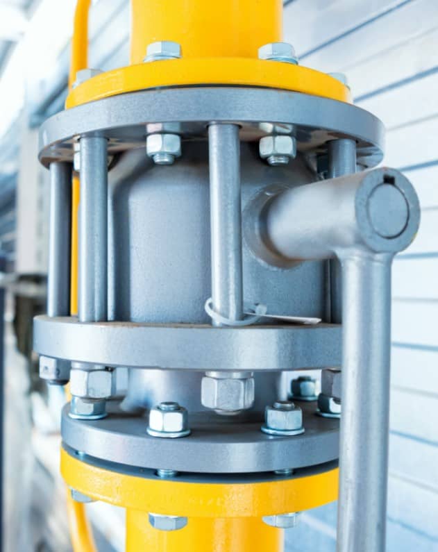
फ्लैंज पाइप, फिटिंग्स (कोहनी, टी आदि), और वाल्व को जोड़ने का यांत्रिक साधन प्रदान करते हैं। वेल्ड्स की तुलना में, फ्लैंज एक गैर-स्थायी प्रकार का जोड़ है जिसे आसानी से असेंबल और डिसअसेंबल किया जा सकता है (उन प्रणालियों के लिए आदर्श जो रखरखाव की आवश्यकता होती है)। फ्लैंज को वेल्डिंग, स्क्रूइंग, या लैपिंग के माध्यम से स्थापित किया जाता है, और वे वेल्डिंग के बाद दूसरा सबसे लोकप्रिय जोड़ने का तरीका हैं।

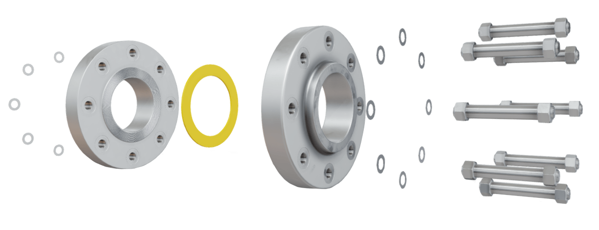
फ्लैंज असेंबली
क्या आप इस लेख का आनंद ले रहे हैं? तो हमारी फ्लैंज फंडामेंटल्स वीडियो कोर्स को अवश्य देखें। इस कोर्स में पांच घंटे से अधिक का वीडियो कंटेंट, 52 पृष्ठों की रंगीन चित्रित पुस्तिका (यह लेख पुस्तिका का एक अंश है), एक क्विज, और कोर्स पूरा करने पर आपको एक प्रमाण पत्र प्राप्त होगा। आनंद लें!
फ्लैंज शब्दावली
फ्लैंज शब्दावली और नामकरण समान शब्दों, परिभाषाओं, और वाक्यांशों के कारण भ्रमित कर सकते हैं। सीखने की प्रक्रिया को आसान बनाने के लिए, पाठकों को निम्नलिखित शब्दों को स्पष्ट रूप से समझना चाहिए:
- फ्लैंज प्रकार – फ्लैंज डिज़ाइन को संदर्भित करता है। फ्लैंज प्रकार के उदाहरणों में वेल्डिंग नेक (वेल्ड नेक), स्लिप-ऑन, सॉकेट वेल्ड, थ्रेडेड, ब्लाइंड फ्लैंज और लैप जॉइंट प्रकार के फ्लैंज शामिल हैं। फ्लैंज प्रकार तापमान और दबाव आवश्यकताओं के आधार पर चुने जाते हैं, और उनकी ज्यामिति द्वारा पहचाने जाते हैं।
- फ्लैंज चेहरे – फ्लैंज की सीलिंग के लिए उपयोग किए जाने वाले क्षेत्र को संदर्भित करता है; आमतौर पर दो विपरीत फ्लैंज चेहरों के बीच एक गैस्केट स्थापित किया जाता है। फ्लैंज चेहरों के उदाहरणों में फ्लैट, उठाया हुआ, रिंग-प्रकार का जॉइंट (RTJ), लैप जॉइंट, टंग और ग्रूव, और मेल और फीमेल डिज़ाइन शामिल हैं।
- फ्लैंज सतहें – फ्लैंज चेहरे की सीलिंग सतह की स्थिति को संदर्भित करता है। एक फ्लैंज चेहरे की सतह स्मूथ, या सेरेटेड1 हो सकती है। एक फ्लैंज चेहरे की सतह की स्मूथनेस को उसके रफनेस एवरेज (Ra) या अर्थमेटिक एवरेज रफनेस हाइट (AARH) द्वारा परिभाषित किया जाता है।
उपरोक्त सभी विषयों पर आगे चर्चा की जाएगी। यह महसूस करना महत्वपूर्ण है कि कई पहलू न केवल किसी विशेष अनुप्रयोग के लिए चुने गए फ्लैंज प्रकार को प्रभावित करते हैं, बल्कि किस चेहरे और किस सतह को भी। उदाहरण के लिए:
- कुछ प्रणालियों को वेल्डेड जोड़ों की आवश्यकता हो सकती है जिन्हें आसानी से निरीक्षण किया जा सकता है (यह हमेशा कुछ फ्लैंज प्रकारों के साथ संभव नहीं है)।
- कुछ फ्लैंज चेहरे उच्च दबाव प्रणालियों के लिए उपयुक्त नहीं हो सकते हैं क्योंकि अधिकतम सीलिंग दबाव बहुत कम है (फ्लैट फेस डिज़ाइन)।
- कुछ सामग्रियों में खराब फिनिश होने की प्रवृत्ति होती है जो एक संबंधित खुरदरी सीलिंग सतह देती है; इन खुरदरी सतहों को एक गैस्केट की आवश्यकता होती है यदि एक लीक टाइट सील प्राप्त की जानी है जैसे कि कास्ट-आयरन फ्लैंज।
फ्लैंज का चयन करते समय, सामग्री को पहले प्रक्रिया आवश्यकताओं को पूरा करने के लिए चुना जाता है, जबकि तापमान और दबाव आवश्यकताओं को तब चुनी गई सामग्री के आधार पर पूरा किया जाता है।
1‘सेरेशन्स’ फ्लैंज के चेहरे की सतह में कटे हुए मशीनयुक्त खांचे होते हैं। गैस्केट सामग्री खांचों में बहती है, जिससे एक अधिक विश्वसनीय सील प्राप्त होती है; खांचे गैस्केट को स्थिर रखने में भी मदद करते हैं।
बोल्टेड, थ्रेडेड और वेल्डेड जोड़ों
फ्लैंज एक प्रकार का बोल्टेड जोड़ों है। अन्य सामान्य प्रकार के जोड़ में थ्रेडेड जोड़ों और वेल्डेड जोड़ों शामिल हैं।
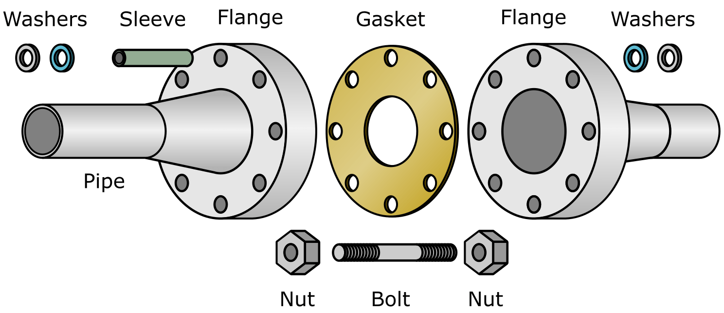
- एक बोल्टेड जोड़ों के लिए एक फ्लैंज और फास्टनर्स (नट्स, बोल्ट्स, या स्टड्स) की आवश्यकता होती है।
- एक थ्रेडेड जोड़ों के लिए एक मेल और फीमेल स्क्रू थ्रेड की आवश्यकता होती है, मेल थ्रेड फीमेल थ्रेड में स्क्रू होता है।
- एक वेल्डेड जोड़ों एक वेल्ड का उपयोग करके बनाया जाता है (धातु को गर्मी लागू करके पिघलाने/फ्यूज करने की प्रक्रिया)।

बोल्टेड जोड़ों
उपयोग किए गए जोड़ों का प्रकार कई कारकों पर निर्भर करता है, जिसमें दबाव, तापमान, प्रक्रिया द्रव का प्रकार, प्रणाली की संचालन विशेषताएँ, और आसपास का पर्यावरण शामिल है। एक बोल्टेड जोड़ों का उपयोग किया जा सकता है यदि:
- अन्य प्रकार के जोड़ों उपयुक्त नहीं हैं जैसे कि वेल्डिंग उन क्षेत्रों में संभव नहीं हो सकती है जो आग या विस्फोट के जोखिम वाले हैं (Ex क्षेत्र); यह ज्यादातर एक पहले से ही संचालन में पाइपिंग प्रणाली के लिए चिंता का विषय है, न कि एक जो निर्माणाधीन है।
- एक मशीनरी आइटम को सेवा लाइन से डिस्कनेक्ट करना आवश्यक है ताकि मशीन का रखरखाव या प्रतिस्थापन हो सके।
- केवल बुनियादी हाथ उपकरणों का उपयोग करके त्वरित फील्ड असेंबली की आवश्यकता होती है।
- जिस आइटम (जैसे टैंक, पाइप, मशीन) से फ्लैंज जुड़ा हुआ है, उसे अक्सर बनाए रखा जाना चाहिए; एक फ्लैंज को डिसअसेंबल और असेंबल करना त्वरित और आसान है, लेकिन वेल्ड नहीं।
एक बोल्टेड जोड़ों से जुड़े कुछ मुख्य नुकसान में शामिल हैं:
- एक बोल्टेड जोड़ों को इंसुलेट करना (थर्मल इंसुलेशन) थ्रेडेड या वेल्डेड जोड़ों की तुलना में अधिक लागत होती है।
- बोल्टेड जोड़ों को थ्रेडेड या वेल्डेड जोड़ों की तुलना में अधिक भौतिक स्थान की आवश्यकता होती है।
- प्रत्येक बोल्टेड जोड़ों एक अतिरिक्त रिसाव बिंदु का प्रतिनिधित्व करता है (भले ही सही तरीके से असेंबल किया गया हो)।
एक सामान्य नियम के रूप में, थ्रेडेड जोड़ों केवल निम्न दबाव और तापमान अनुप्रयोगों के लिए उपयुक्त हैं, जबकि बोल्टेड और वेल्डेड जोड़ों उच्च दबाव और उच्च तापमान अनुप्रयोगों के लिए उपयुक्त हैं। यदि एक थ्रेडेड जोड़ों को लीक टाइट होना चाहिए, और रिसाव बर्दाश्त नहीं किया जा सकता है, तो इसे सील वेल्डेड किया जा सकता है। सील वेल्डिंग तकनीक केवल उच्च सेवा दबाव स्थितियों के लिए उपयोग की जाती है और यह एक आदर्श समाधान नहीं है क्योंकि यह एक तनाव एकाग्रता बिंदु बनाता है जो थकान विफलता के लिए प्रवण होगा।
वेल्डेड जोड़ों के साथ लाभ यह है कि वेल्ड को गैर-विनाशकारी परीक्षण (NDT) तकनीकों का उपयोग करके साबित किया जा सकता है जैसे कि पेनेट्रेंट परीक्षण, अल्ट्रासोनिक परीक्षण, मैग्नेटिक पार्टिकल परीक्षण, हाइड्रोस्टेटिक प्रेशर परीक्षण आदि; एक फ्लैंज -और फ्लैंज गैस्केट- को साबित करना अधिक कठिन है।
फ्लैंज निर्माण
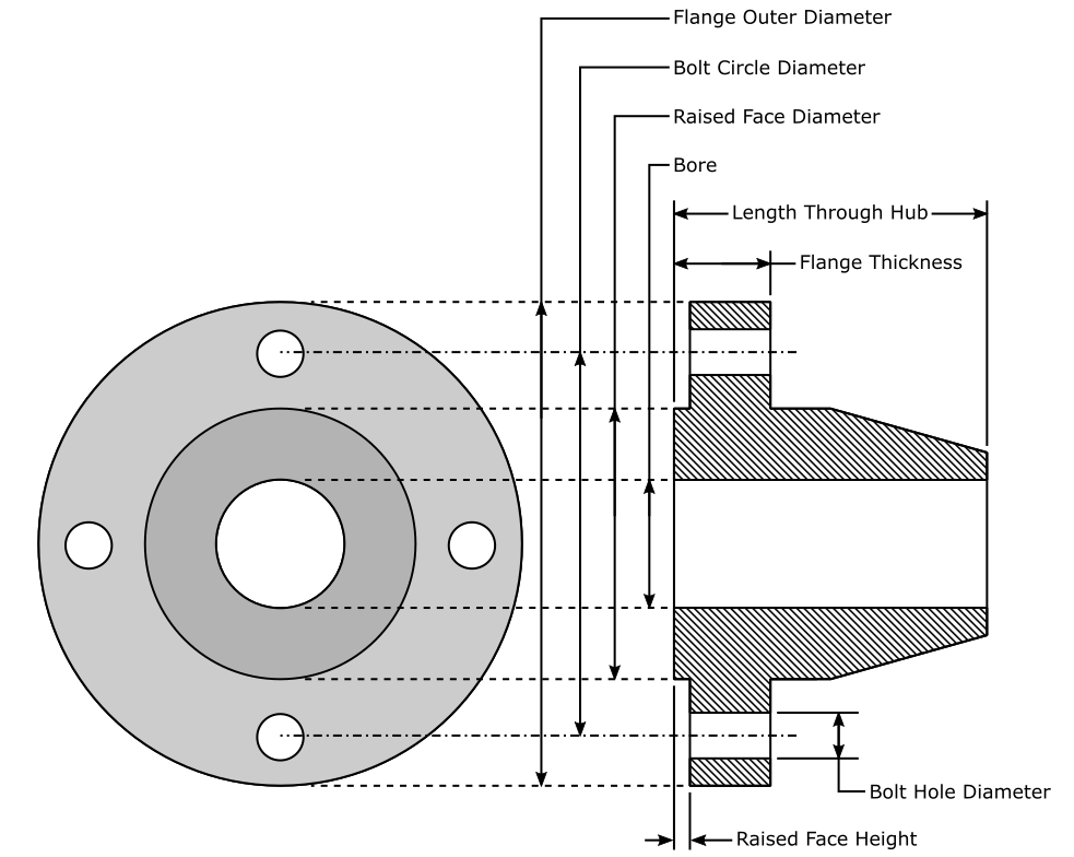
फ्लैंज को दो मुख्य क्षेत्रों में विभाजित किया जाता है, ‘ब्लेड’, और ‘हब’।
- फ्लैंज ब्लेड उस क्षेत्र को शामिल करता है जहां बोल्ट फ्लैंज और फ्लैंज चेहरे के माध्यम से प्रवेश करते हैं।
- फ्लैंज हब वह क्षेत्र है जो पाइप को समायोजित करता है जो फ्लैंज से जुड़ता है।
यह सुनिश्चित करने के लिए कि मिलान करने वाले2 फ्लैंज के बीच कोई रिसाव न हो, गैस्केट्स का उपयोग किया जाता है। यह दो धातु फ्लैंज को गैस्केट्स के बिना मिलाने के लिए संभव है, लेकिन सीलिंग कठिन है और केवल विशेष रूप से डिज़ाइन किए गए फ्लैंज के साथ ही प्राप्त की जा सकती है।
अंत कनेक्शन निर्दिष्ट करता है कि फ्लैंज अपने साथ के पाइप से कैसे जुड़ा है (थ्रेडेड कनेक्शन या वेल्डेड)।

फ्लैंज डिज़ाइन
2मिलान करना – दो विपरीत फ्लैंज चेहरे की सीलिंग सतहों को एक साथ दबाने को संदर्भित करता है।
फ्लैंज कैसे काम करते हैं
एक फ्लैंज तब बनाया जाता है जब दो विपरीत सतहों को जानबूझकर एक लीक टाइट सील बनाने के लिए एक साथ दबाया जाता है। सील प्राप्त करने के लिए, प्रत्येक विपरीत फ्लैंज चेहरे पर बल लगाया और बनाए रखा जाना चाहिए। चूंकि कई फ्लैंज चेहरों में निर्माण दोष होते हैं (खरोंच, डेंट, गड्ढे आदि), सील प्राप्त करने के लिए दो मिलान करने वाली सीलिंग सतहों के बीच एक नरम सामग्री डालना आवश्यक है; यह नरम सामग्री गैस्केट है।

फ्लैंज असेंबली
मूल फ्लैंज गणित
यह समझने के लिए कि फ्लैंज कैसे काम करते हैं, हमें पहले दबाव की अवधारणा को समझना होगा। दबाव को परिभाषित किया जाता है:
दबाव = बल / क्षेत्र
P = F / A
फ्लैंज सील करते हैं क्योंकि दबाव मिलान करने वाली सीलिंग सतहों पर लगाया जाता है; इस दबाव को ‘गैस्केट संपीड़न’ या ‘सीलिंग दबाव’ के रूप में जाना जाता है। लगाया गया दबाव दो चेहरों को या तो:
- दो मिलान करने वाले चेहरों के बीच एक गैस्केट को कुचलता है।
- दो मिलान करने वाले चेहरों को एक-दूसरे के खिलाफ दबाता है।
गैस्केट के उदाहरण में, गैस्केट लगाए गए दबाव के कारण विकृत हो जाता है; यह विकृति गैस्केट को किसी भी सतह दोषों में ‘बहने’ का कारण बनती है जो किसी भी सीलिंग चेहरे पर मौजूद हो सकती है। चूंकि सतह दोष गैस्केट सामग्री द्वारा भरे गए हैं, रिसाव अब संभव नहीं है।
दूसरा उदाहरण मानता है कि कोई गैस्केट मौजूद नहीं है और दो फ्लैंज चेहरे एक साथ दबाए गए हैं। इस विधि का उपयोग करके एक लीक टाइट सील बनाना कठिन है, हालांकि यह संभव है यदि सतहें अच्छी तरह से मशीन की गई और बहुत साफ हैं। लगाया गया सीलिंग दबाव अक्सर महत्वपूर्ण होना चाहिए, क्योंकि फ्लैंज सतह धातु से निर्मित हो सकती है, जो दबाव के तहत आसानी से विकृत नहीं होती है (सामग्री और फ्लैंज वर्ग पर निर्भर)। धातु से धातु फ्लैंज चेहरे की सीलिंग महंगी है और इसलिए सामान्य नहीं है।
आवश्यक सीलिंग दबाव बनाने के लिए, बल और क्षेत्र के चर को समायोजित किया जा सकता है।
- बल मिलान करने वाले फ्लैंज चेहरों पर टाइटनिंग टॉर्क (बोल्टिंग लोड) को संदर्भित करता है जब फ्लैंज असेंबली पर नट्स को टाइट किया जाता है। बल (F) टॉर्क (T), टॉर्क घर्षण (K) और नाममात्र बोल्ट व्यास (D) पर निर्भर करता है। वर्णित बल को ‘बोल्ट प्रीटेंशन’ या ‘बोल्ट प्रीलोड’, या ‘बोल्ट प्रीस्ट्रेस’ के रूप में वर्गीकृत किया जाता है, और इसे समीकरण F = T/(KD) द्वारा दर्शाया जाता है।
- क्षेत्र सीलिंग चेहरे के क्षेत्र के आकार को संदर्भित करता है।
फ्लैंज सीलिंग चेहरों पर दबाव की मात्रा फ्लैंज असेंबली को टाइट करते समय लगाए गए बल की मात्रा से मेल खाती है। इस प्रकार यह असेंबली के दौरान बोल्ट को टाइट करते समय लगाए गए प्रयास की मात्रा को समायोजित करके दबाव को नियंत्रित करना संभव है।
फ्लैंज का सीलिंग क्षेत्र असेंबली के दौरान उपयोग किए गए बल के रूप में आसानी से समायोजित नहीं किया जा सकता है। एक बड़ा सीलिंग चेहरा एक निश्चित मात्रा में दबाव प्राप्त करने के लिए अधिक बल की आवश्यकता होती है, जब एक छोटे सीलिंग चेहरे का उपयोग किया जाता है। नीचे दिया गया उदाहरण इस बिंदु को उजागर करता है, लेकिन इकाइयों के उपयोग के बिना।
उदाहरण
एक दिए गए फ्लैंज असेंबली को सील करने के लिए 10 का दबाव आवश्यक है। यह एक छोटे सीलिंग चेहरे पर बहुत अधिक बल लागू करके प्राप्त किया जा सकता है:
दबाव = बल / क्षेत्र
10 = 40 / 4
या, यह सीलिंग चेहरे के आकार (क्षेत्र) को घटाकर और इस प्रकार समान मात्रा में दबाव बनाने के लिए आवश्यक बल की मात्रा को कम करके प्राप्त किया जा सकता है3:
10 = 20 / 2
दबाव, बल, और क्षेत्र के बीच संबंध को संक्षेप में प्रस्तुत किया जा सकता है:
सीलिंग चेहरे के क्षेत्र को घटाने से एक दिए गए दबाव की मात्रा बनाने के लिए आवश्यक बल में कमी होती है।
सीलिंग चेहरे के क्षेत्र को बढ़ाने से एक दिए गए दबाव की मात्रा बनाने के लिए आवश्यक बल में वृद्धि होती है।
फ्लैंज असेंबली पर लागू किए जा सकने वाले बल की मात्रा भौतिक शक्ति (नट्स अक्सर हाथ से टाइट किए जाते हैं), गैस्केट ब्लो-आउट4, और फ्लैंज बोल्ट थ्रेड्स के 5 के स्ट्रिपिंग से संबंधित समस्याओं के कारण सीमित है; लेकिन इन समस्याओं को सीलिंग चेहरे के आकार को घटाकर दूर किया जा सकता है। उपयोग किए गए सीलिंग चेहरे का प्रकार और आकार प्रासंगिक पाइपिंग मानकों द्वारा निर्धारित किया जाएगा जब फ्लैंज का तापमान और दबाव रेटिंग ज्ञात हो।
इस खंड में चर्चा की गई बातों के आधार पर, यह निर्धारित किया जा सकता है कि उच्च दबाव पर सील करने के लिए आवश्यक फ्लैंज में छोटे सीलिंग चेहरे होते हैं। एक दर्शक प्रणाली के संचालन के दबाव का अनुमान लगा सकता है फ्लैंज सीलिंग चेहरों का दृश्य निरीक्षण करके जैसे कि बड़े फ्लैंज सीलिंग चेहरे निम्न दबाव प्रणालियों को इंगित करते हैं।3मानक जैसे ASME B16.5 और B16.47 आवश्यक सीलिंग चेहरे के आकार को निर्धारित करते हैं।
4सीलिंग चेहरे से गैस्केट के निष्कासन को दबाव के कारण संदर्भित करता है; यह आमतौर पर असेंबली के दौरान फ्लैंज के अधिक टाइटनिंग के कारण होता है।
5स्टड या बोल्ट से थ्रेड्स को हटाने को संदर्भित करता है; परिणामस्वरूप एक गोलाकार टुकड़ा होता है जिसमें कोई स्क्रू थ्रेड्स नहीं होते हैं।
फ्लैंज परिभाषित करने वाले कारक
फ्लैंज कुछ मानदंडों के आधार पर वर्गीकृत किए जाते हैं, और ये श्रेणियाँ आमतौर पर प्रासंगिक पाइपिंग मानकों और विशेषताओं द्वारा परिभाषित की जाती हैं (बाद में चर्चा की जाएगी)। एक फ्लैंज को परिभाषित किया जाता है
- प्रकार – फ्लैंज की समग्र ज्यामिति। वेल्डिंग नेक, स्लिप-ऑन, और सॉकेट वेल्ड, विभिन्न फ्लैंज प्रकारों के उदाहरण हैं।
- चेहरा – फ्लैंज का सीलिंग क्षेत्र। फ्लैट फेस, उठाया हुआ फेस, और रिंग प्रकार का जॉइंट, विभिन्न फ्लैंज चेहरों के उदाहरण हैं।
- मानक और विशेषताएँ – फ्लैंज दिए गए मानकों और विशेषताओं का पालन करने के लिए निर्मित होते हैं। मानक और विशेषताएँ एक दिए गए फ्लैंज के आयाम, ज्यामिति, शेड्यूल, और सामग्री को निर्धारित करते हैं (कुछ कारकों का नाम)।
- आयाम – एक फ्लैंज के हब, चेहरे, ब्लेड आदि के आयाम। आयाम नाममात्र पाइप आकार (NPS) और एक दिए गए अनुप्रयोग के लिए आवश्यक दबाव वर्ग पर निर्भर करते हैं।
- नाममात्र पाइप आकार (NPS) – एक माप की आयामहीन इकाई जो उस आइटम (पाइप, फिटिंग आदि) के आकार को परिभाषित करती है जो फ्लैंज से जुड़ता है।
- दबाव वर्ग – एक दिए गए सामग्री के लिए फ्लैंज का दबाव-तापमान रेटिंग। 'दबाव वर्ग' नाम के बावजूद, यह कारक सामग्री और तापमान पर निर्भर है।
- सामग्री – फ्लैंज जिस सामग्री से निर्मित होता है जैसे कि कास्ट आयरन, कार्बन स्टील, स्टेनलेस स्टील आदि।
- शेड्यूल (SCH) – एक पाइप की मोटाई/शेड्यूल। पाइप का शेड्यूल केवल वेल्डिंग नेक और लैप-जॉइंट फ्लैंज के लिए प्रासंगिक है क्योंकि इन फ्लैंज का शेड्यूल उस संबंधित पाइप शेड्यूल से मेल खाना चाहिए जिससे वे जुड़े होते हैं। अन्य फ्लैंज प्रकार या तो आंशिक रूप से स्लाइड करते हैं, स्क्रू करते हैं, या अपने संबंधित फ्लैंज के माध्यम से प्रवेश करते हैं, इसलिए फ्लैंज शेड्यूल को पाइप शेड्यूल से मेल खाने की आवश्यकता नहीं है। शेड्यूल स्विवल-रिंग फ्लैंज के लिए प्रासंगिक है, लेकिन इनका सीमित अनुप्रयोग होता है और आगे चर्चा नहीं की जाएगी।
उपरोक्त सभी बुलेट पॉइंट्स को आने वाले खंडों में तार्किक क्रम में चर्चा की जाएगी। फिलहाल, यह महसूस करना महत्वपूर्ण है कि फ्लैंज अद्वितीय आइटम नहीं हैं। फ्लैंज एक विशिष्ट उद्देश्य के लिए निर्मित होते हैं, जिसमें कई डिज़ाइन कारकों पर पहले ही विचार किया जा चुका है। यदि कोई फ्लैंज कभी विफल हो जाता है, तो उसी फ्लैंज को -सैद्धांतिक रूप से- उसके पूर्ववर्ती को बदलने के लिए आदेश दिया जा सकता है6; इसका महत्वपूर्ण वास्तविक दुनिया के लाभ हैं, जिन पर बाद में मानकीकरण खंड में चर्चा की जाएगी।
6किसी भी फ्लैंज पर जो अप्रत्याशित रूप से विफल हो गया है, एक रूट कॉज़ एनालिसिस (RCA) किया जाना चाहिए। यदि विफलता का कारण निर्धारित नहीं किया जाता है, तो एक नए फ्लैंज के साथ भी वही विफलता फिर से हो सकती है।
फ्लैंज प्रकार, चेहरे, और सतहें - समझाया गया!
यह वीडियो हमारे पाइपिंग फ्लैंज फंडामेंटल्स वीडियो कोर्स का हिस्सा है
संबंधित ऑनलाइन इंजीनियरिंग कोर्स
वाल्व्स का परिचय (संक्षिप्त कोर्स)
न्यूमेटिक वाल्व्स कैसे काम करते हैं
मल्टीस्टेज सेंट्रीफ्यूगल पंप्स कैसे काम करते हैं
प्लेट हीट एक्सचेंजर फंडामेंटल्स
प्लेट हीट एक्सचेंजर्स कैसे काम करते हैं
सब-क्रिटिकल, सुपरक्रिटिकल, और अल्ट्रा-सुपरक्रिटिकल बॉयलर्स
हीट रिकवरी स्टीम जनरेटर्स समझाया गया
अतिरिक्त संसाधन
http://www.wermac.org/flanges/flanges_raised-face_flat-face_ring-type-joint.html
